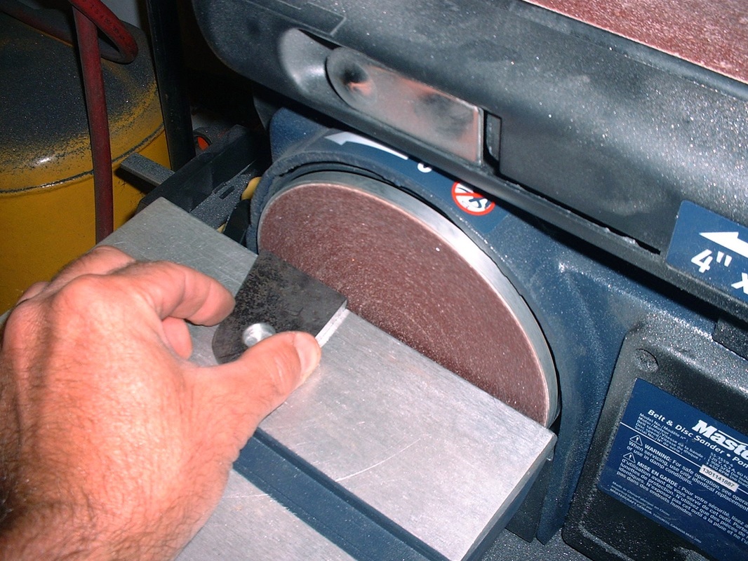
As with the lower link mounts, I cut the upper link mounts from 3/16" steel plate using an angle grinder with a cut-off wheel, then did the final shaping with a disk and belt sander:
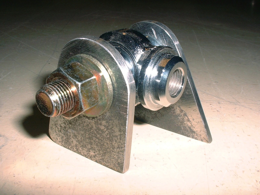
Then, to get the correct spacing and alignment between the mounting ears, I mocked them up using an old spherical rod end I had lying around and tightened everything together with a 1/2" bolt. This is a forward mount:
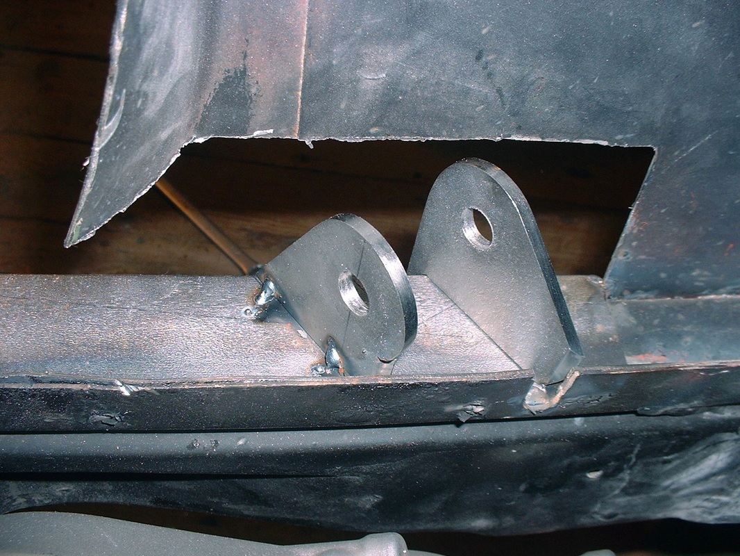
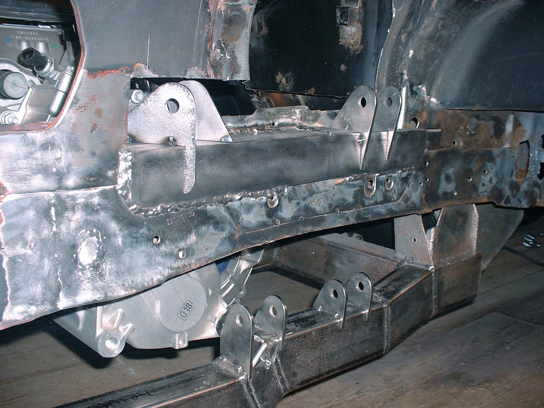
The forward mount sits at a 51 degree angle to the centreline of the car, but the frame rail also diverges from the car's centreline in that area by 7 degrees, so it took me a few tries before I was able to clamp the mounting ears in place with the holes at the right height, angle, depth, and lateral coordinates. Once I was certain of the alignment, I tack welded the upper link mounts to the frame stiffener:
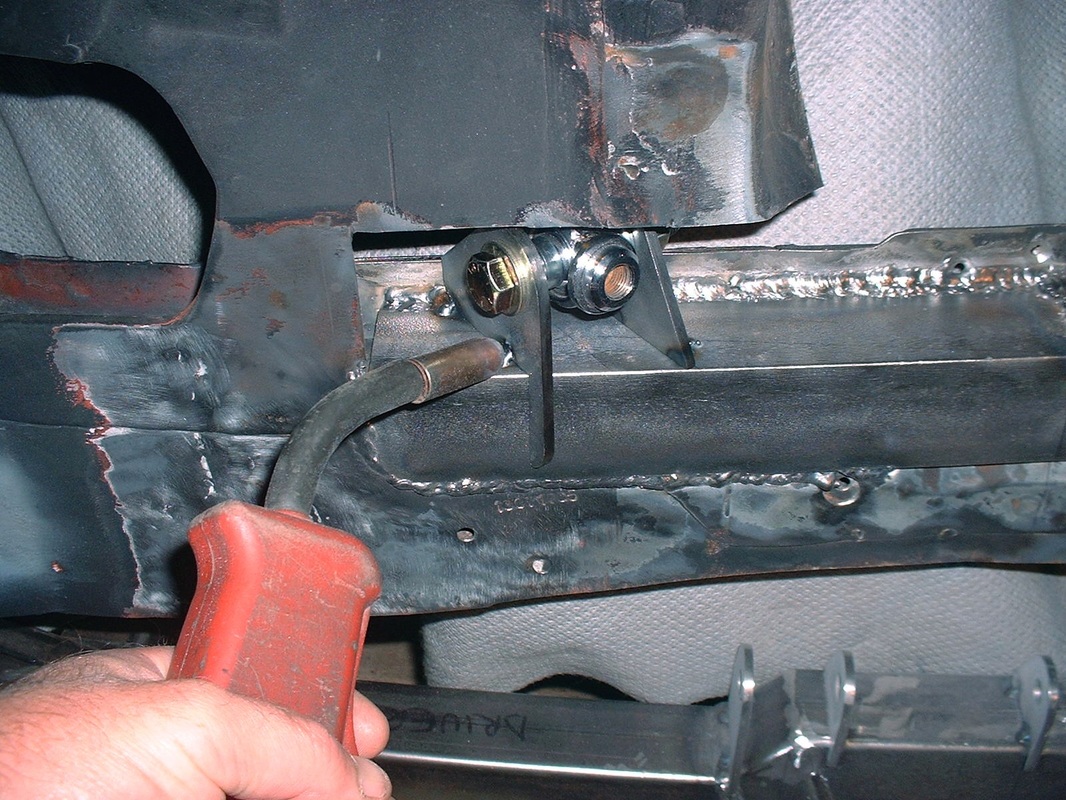
This is the view of the same mount as seen from the engine bay looking outwards:
The rear link mounts were easier since they only needed to be perpendicular to the centreline of the car. Here are all four sets of mounts tacked in place on the driver's side of the frame. This view is looking toward the rear:
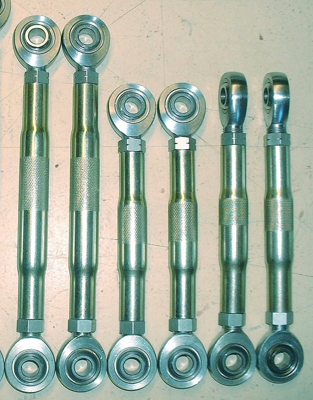
The next step was to build up the links to the correct lengths. I set about screwing the jamb nuts on all the rod ends, then threading the rod ends into each of the swaged tubes. I had printed a legend to remind me how long each link needed to be eye-to-eye. I like to go by the rule of thumb that a rod end should be threaded into a swaged tube over a length at least equal to 1.5 times the diameter of the threads. Here are the upper links and the pushrods ready for installation. In order from left to right are the upper trailing links (forward), the upper lateral links (rear), and the pushrods. Notice they have their rod ends turned 90 degrees to each other:
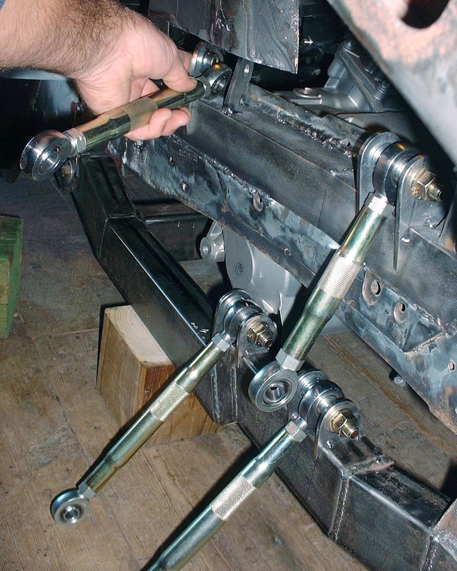
I then simply attached the two upper and two lower links to their respective mounts on the frame using a 1/2" diameter fine threaded grade 8 bolt and a pair of rod end spacers per mount. I made sure to buy bolts that were unthreaded along the length between the mounting ears, which for the most part, meant buying extra long bolts and cutting them down to fit correctly:
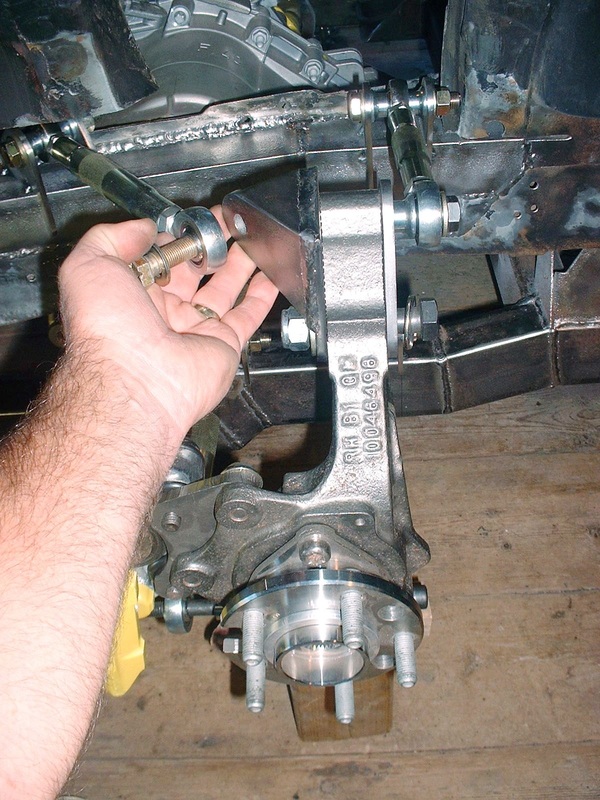
Then attached the knuckle to the links:
Here's what the system looked like with all five links and the pushrod mocked up and ready for final welding of the mounts:
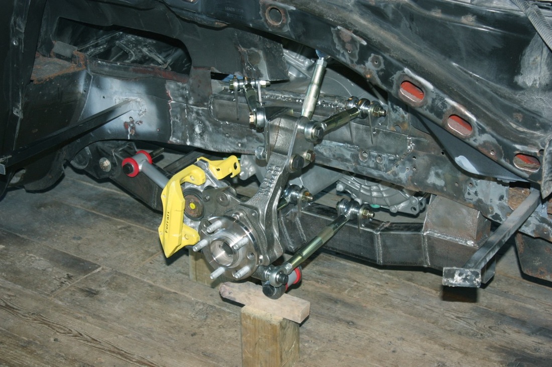
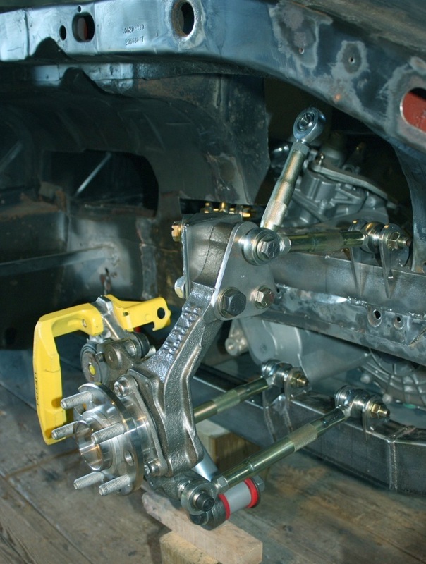
And a close up:
These five links control the range and direction of the movement of the wheel so I was able to run through a preliminary test, cycling the suspension through its range of travel. I was quite happy that the wheel appeared to be doing as it was designed with the correct camber gain and no binding of the spherical rod ends or links. The upper frame rail still needed to be notched for full jounce testing and of course other issues such as axle clearance had to be sorted out but all that would come later. I had a working 5-link design!
While the links control the range and direction, the shock absorber and spring control the rate of the movement. That was the next hurdle... mounting the bell crank and shock.

 RSS Feed
