Mounting the bell crank was one of those jobs that caused me to take two steps backwards before I could take one forward. As I mocked up a cardboard template of the bell crank (it was easier to handle than the steel one!), I realized I had to address a problem I had been ignoring: rust on the inner wall of the upper frame rail where the strut tower used to be:
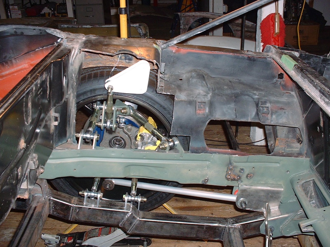
The driver's side was the worst but I had to address both sides as part of the bell crank mount design.
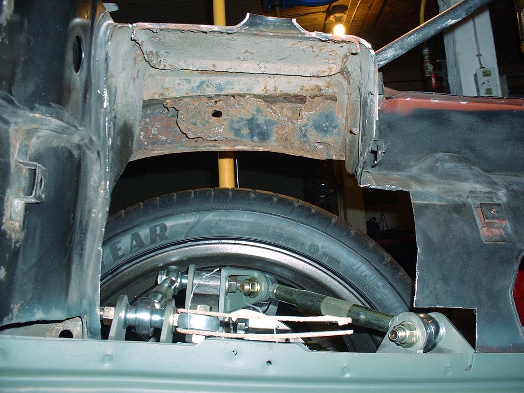
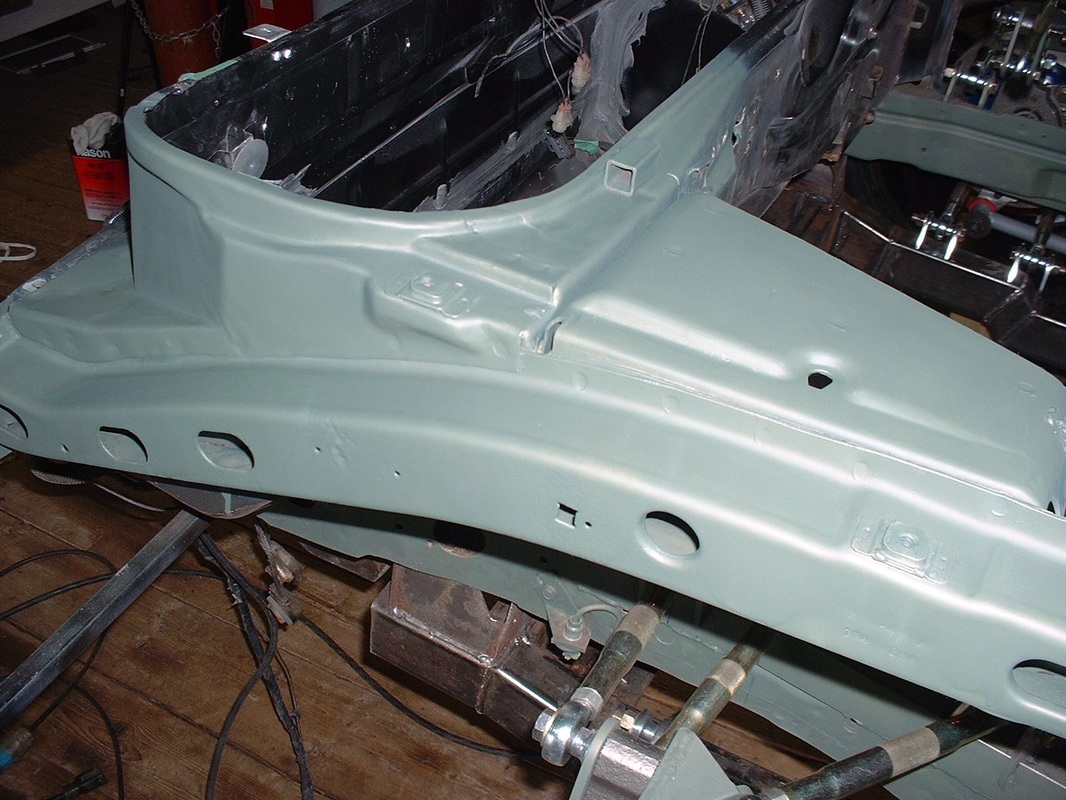
Once I gained access to the inside of the upper frame rail, I could see that the rust was limited to the area right around the strut tower, and except for the inside wall which I cut away, the rest was only surface rust. Replacing the entire upper frame rail luckily wasn't necessary. Here's how it looked after localized sandblasting and priming:
The inner wall of the frame rail which was completely rusted out would be replaced as an integral part of the frame stiffener for the upper bell crank mount.
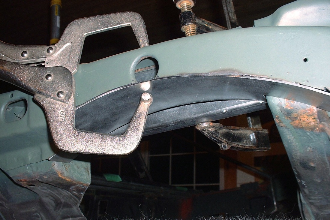
The rusty condition in that area led me to be a little concerned about the integrity of the entire area though, since much of it is covered in OEM seam sealer. This is the top side of the upper frame rail where it is joined to the former strut tower:
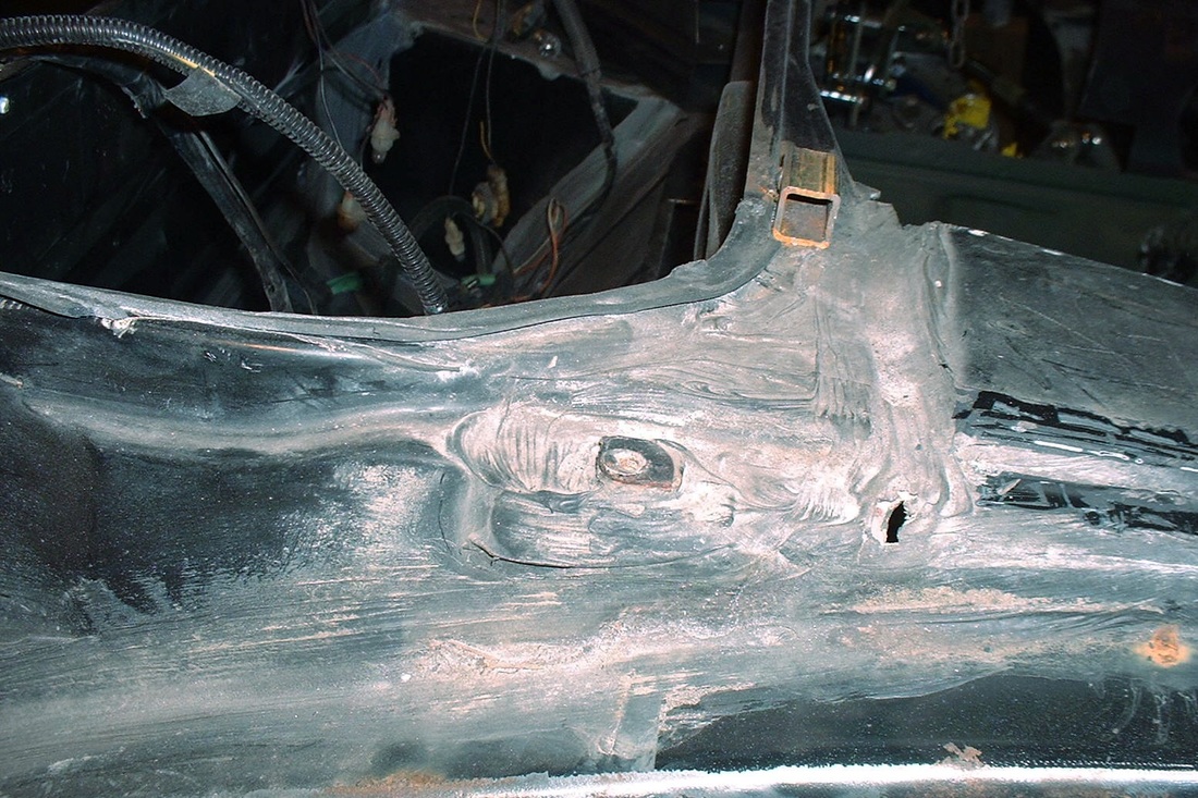
To be on the safe side, I decided to remove all of the sealer on both rails to get a feel for how deep the corrosion might have gone between these interconnecting structures:
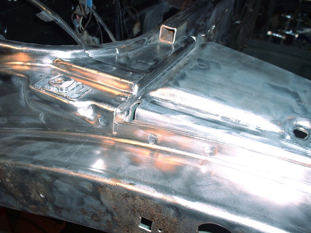
I was happy to find that the rust was limited to the one area I'd already addressed. After priming, I had peace of mind to continue my plan to install the upper bell crank mount to this general area.
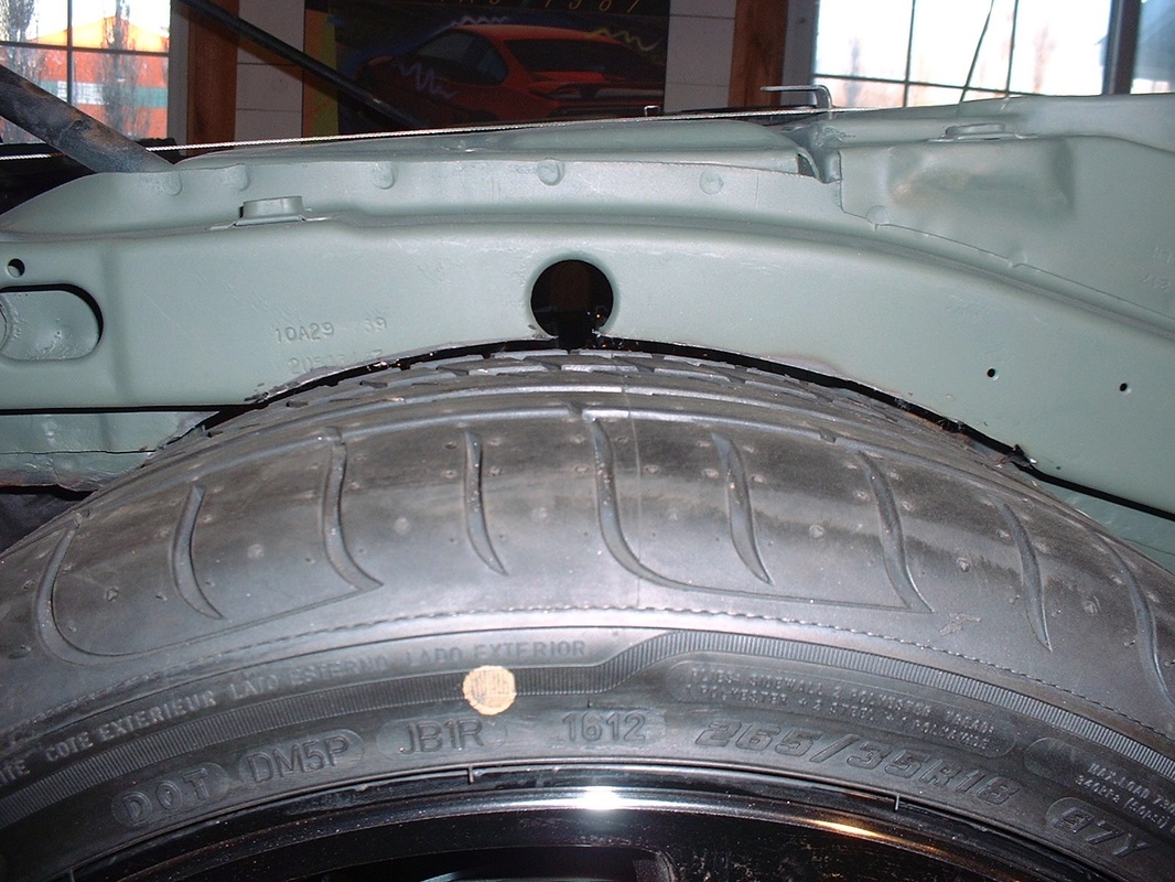
The next thing was to make the necessary frame notch to the underside of the upper frame rail to allow the tire to move into it's full range of jounce.
I used an angle grinder with a cut-off wheel to carefully cut away the steel:
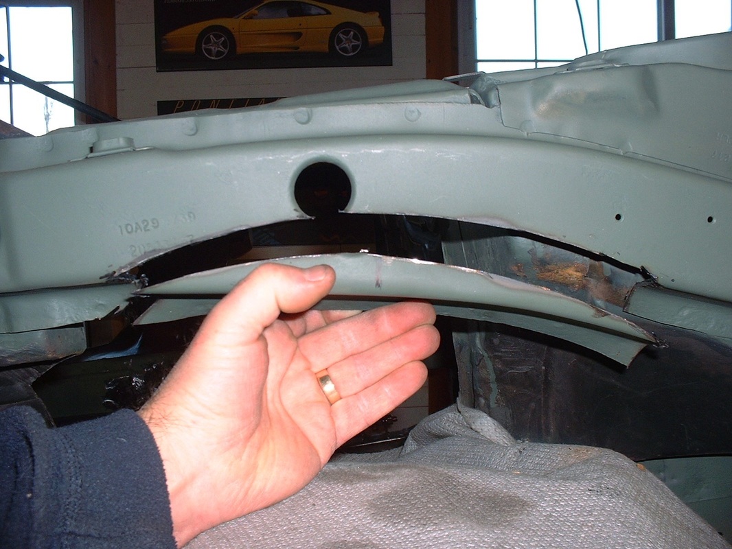
Then cycled the suspension up to make certain the tire would clear:
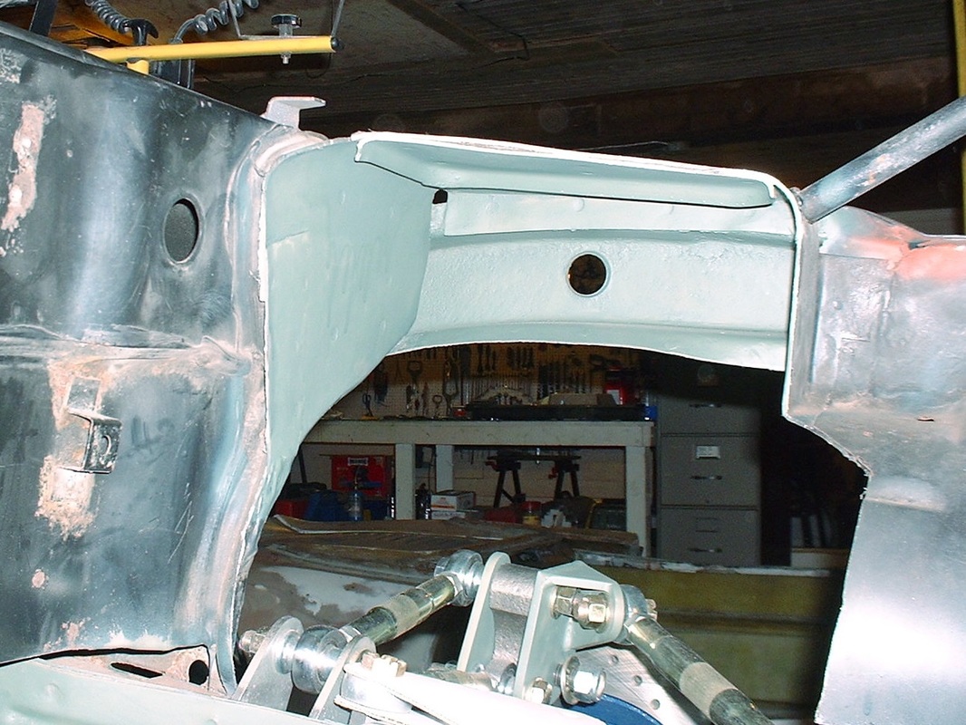
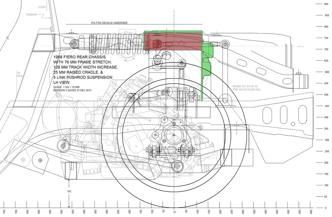
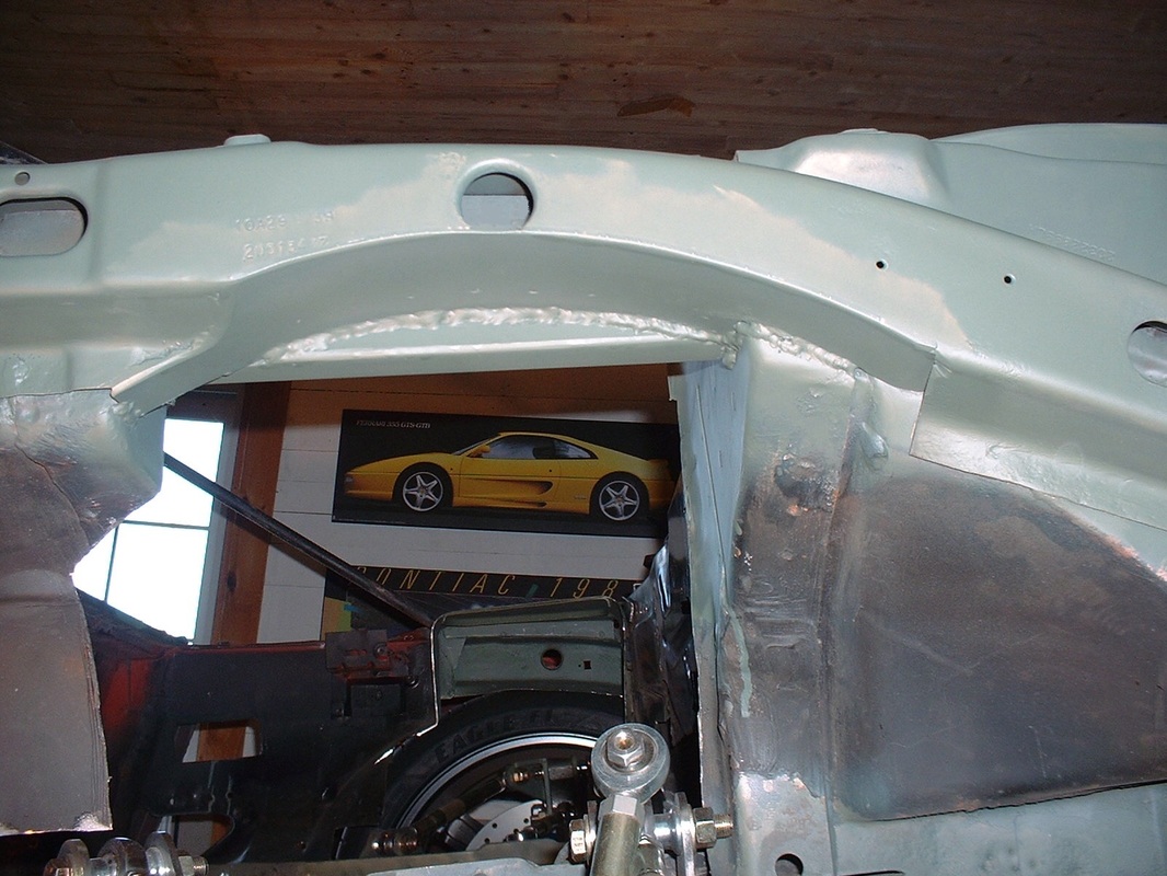
So, with the inboard and bottom walls of the frame rail removed completely, and the outside wall reduced to about half of it's original height, my next step was to regain the structural rigidity I'd removed. My solution was to use a 2" x 3" x 1/8" wall rectangular tube (red stucture) to bridge the space between the strut tower brace (integral with the trunk and aft strut tower wall) and the forward strut tower wall (green structure), like so:
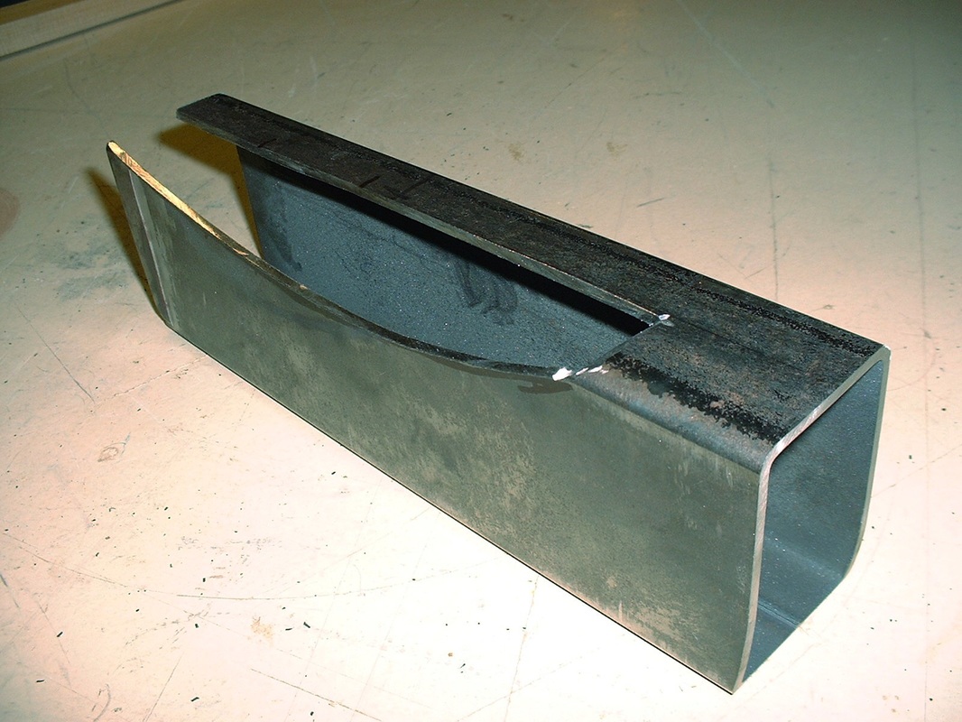
I still had to notch the new stiffener for tire clearance:
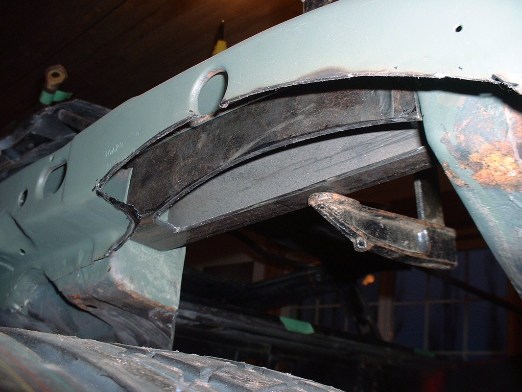
But from this view you can see how much wider the frame rail will be than before, and how there are now three vertical walls that will make up the rail:
To box the upper frame rail and the stiffener, I made a cardboard template to mock up the shape of the floor that will bridge the stiffener to the frame rail and close off the area. Once I was happy with the fit, I traced the shape onto some 1/8" thick steel plate, cut it out, and rolled it to the right curvature:
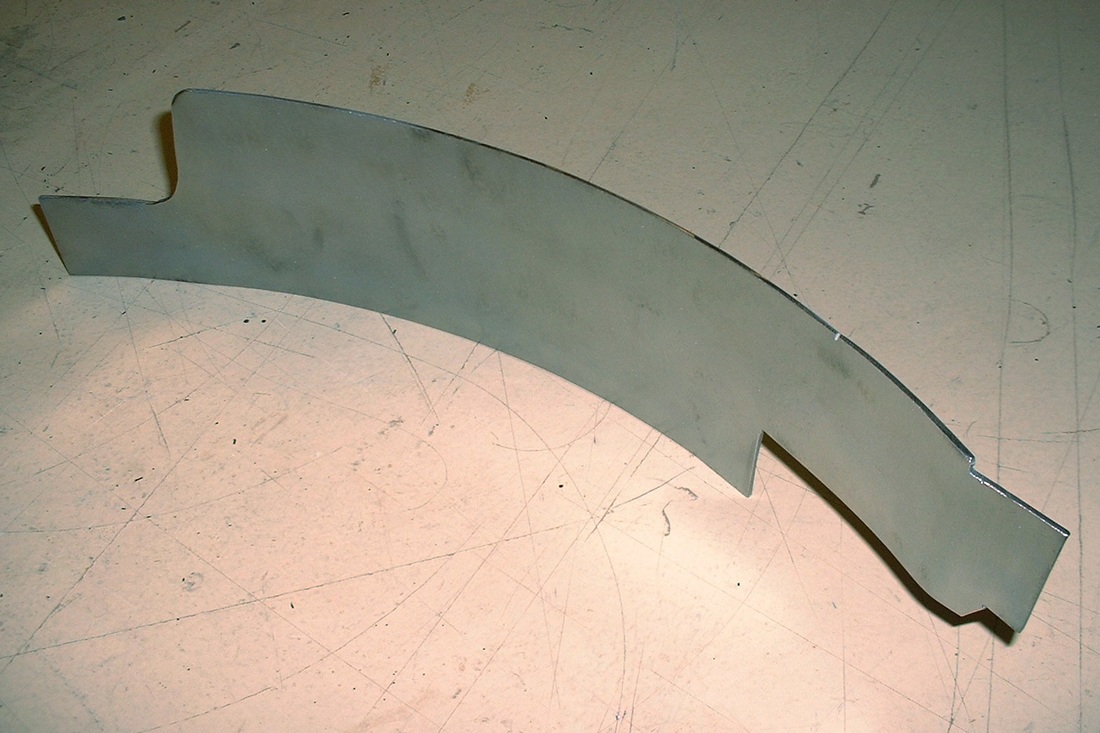
Here's what the rail's floor piece looked like mocked up. I wanted to weld the floor piece to all three vertical walls (the original outside wall, plus the two walls of the stiffener) for added rigidity. The way I accessed the middle wall with the welder was by drilling some small holes in the floor in-line and underneath it, and rosette-welded the two together despite very limited access once the floor was in place. I also primed and painted the inside surfaces before it got welded up too:
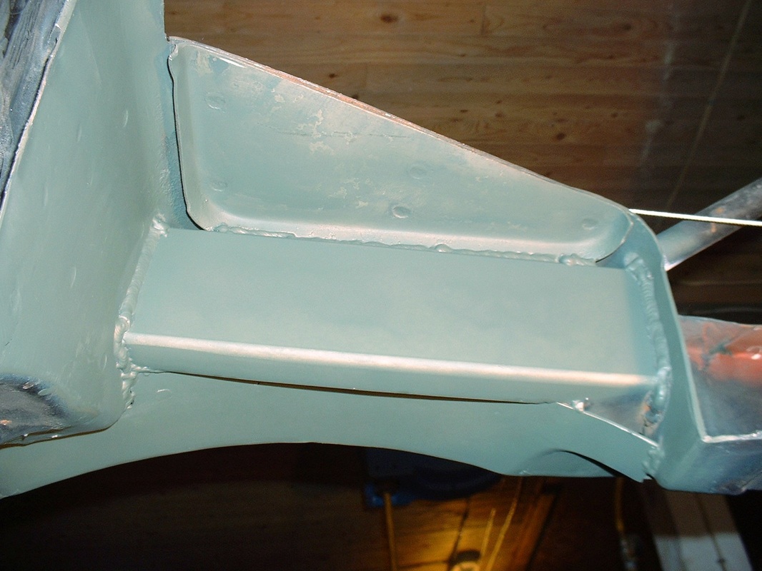
Here's the completed frame notch and upper bell crank mount stiffener:
And here's the view from the inside of the engine bay:

 RSS Feed
