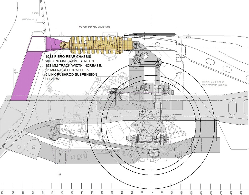
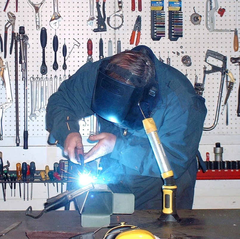
I was finally ready to work on the last piece of the puzzle, namely, the shock absorber mounts. My plan was to replace an OEM cross car beam under the rear window with a much stiffer beam that could react the loads of the springs and shocks. In the drawing below, this new cross car beam (shown in cross section) will serve as a solid mount for the stationary end of the coil-overs, the two engine torque struts, the deck lid hinges, and the new Toyota MR2 rear glass. It will be welded to the two upper frame rails at either end and supported by two slanted vertical beams (pink members) welded to the lower frame rails like so:
The OEM beam was formed from two Z sections spot-welded together. I only needed to remove the lower half so it was a matter of drilling out several dozen spot welds:
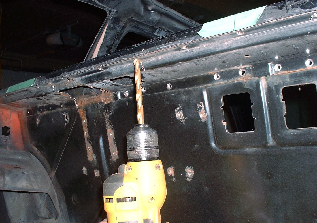
Here's an overview showing the lower half dangling after drilling out the last few spot welds:
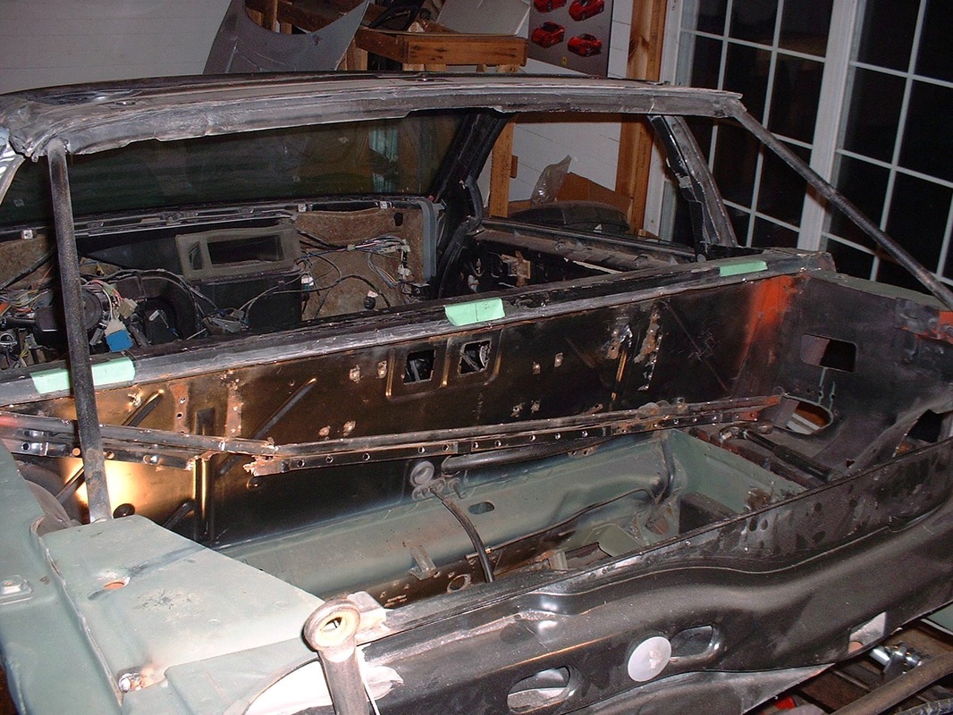
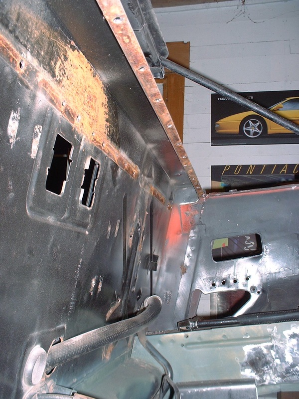
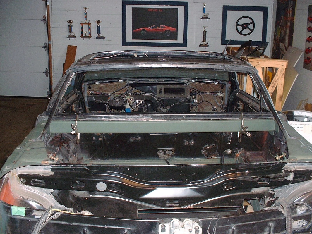
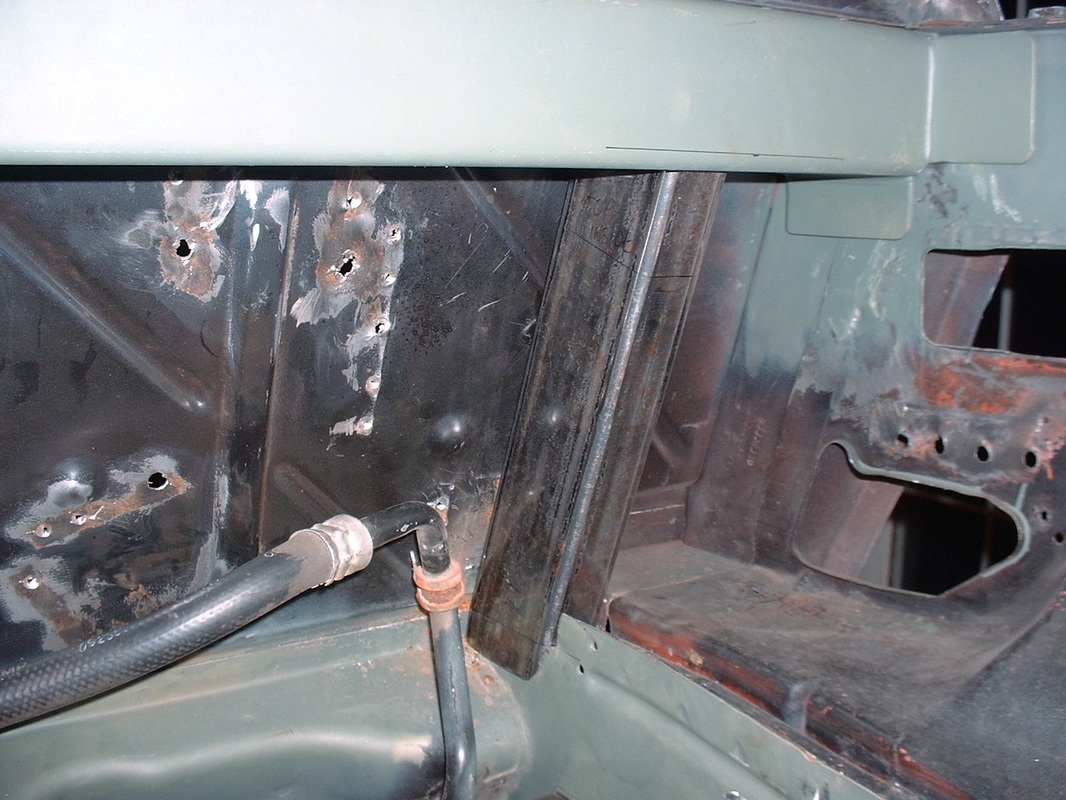
Here's what the firewall looked like without the lower half of the OEM cross-car beam. The surface rust would be sanded off and the entire firewall re-primed later:
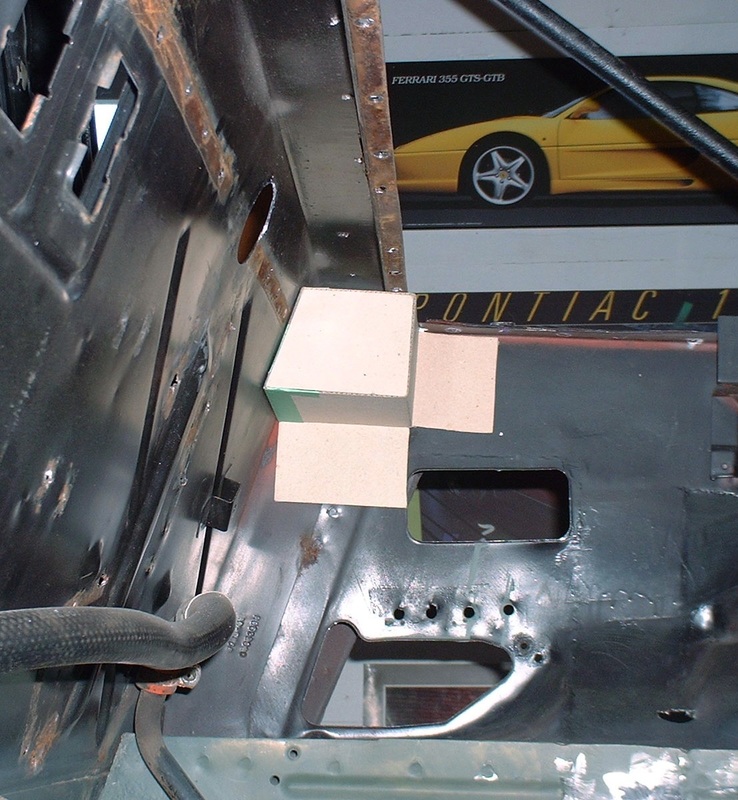
I made a cardboard template to mock up the new cross car beam shape and determine where I would need some flanges on the cross member to weld it to the chassis:
I used a rectangular tube as the basis for the cross member but since the firewall is sloped at about 18 degrees from vertical, the tubing had to be modified to fit the firewall snugly yet have the rear edge vertical. I bought the materials I'd need: 60" of 3" x 4" x 1/8 wall rectangular tubing (not a particularly popular size at your local metal supplies shop!) and the same length of some 3" x 1/8" flat bar:

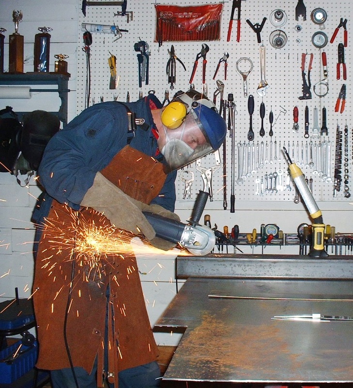
To make the right angled trapezoidal shape of the cross member, I lopped off all of one of the 3" walls of the tubing, and a portion of the adjacent 4" wall using a cut off wheel in an angle grinder:
The next step was to bend some flanges at either end:
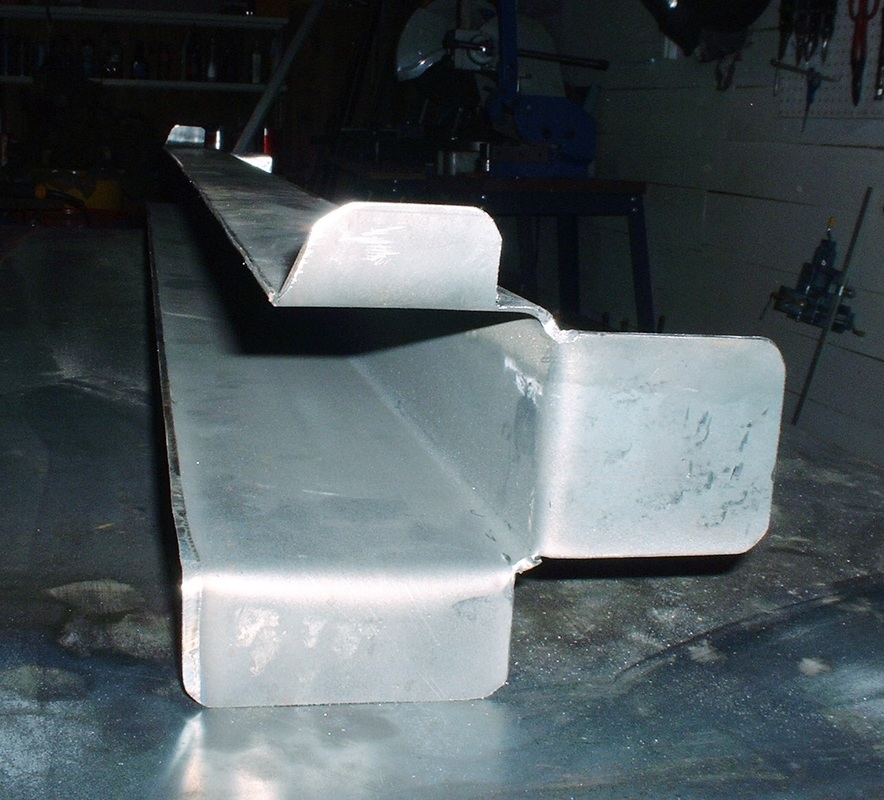
I wanted to prime the inside of the beam so that was easiest while the fourth side was not yet welded on:
I then tacked the 3" x 1/8" steel bar to the tube in many places to keep it from deforming while final welding it, then hit it up with a full zap:
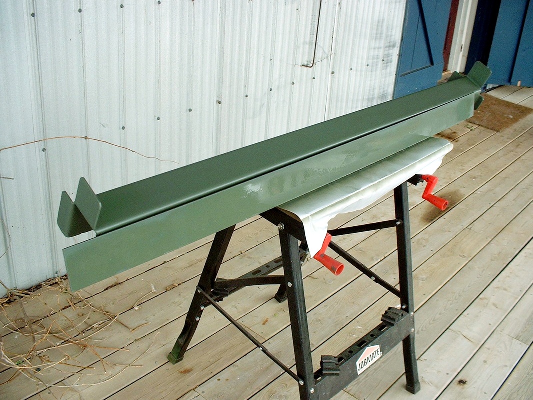
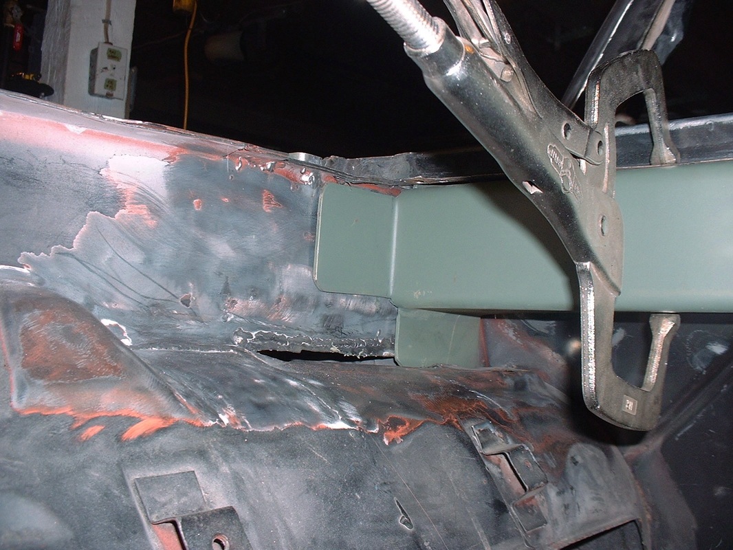
By this time I had already trial-fitted the new firewall cross member a dozen times so I was getting good at knowing just how to wiggle and jiggle it into place, and just where to hit it with the rubber mallet to seat it. Here's the final mock up before tack welding it:
And a close up of how the end flanges tied into the upper frame rail:
Next up was cutting and fitting the two vertical supports for the new cross member. They connect the lower frame rail to the underside of the new cross member and react the loads of the springs. I made a couple of cardboard templates and after trial fitting them several times I cut the 1" x 3" x 1/8" tubing and mocked them up... this is the passenger side:
The final step was to make the stationary shock absorber mounts. I needed to figure out what height the eyes of the mounts had to be at to keep the shock level, then where along the length of the new cross member they had to be installed to ensure the shocks would be parallel to the frame, and finally how far back the mounting eyes had to ensure the shock absorber would be 14-1/2" long with the suspension at ride height. Again, I fabbed up some cardboard templates and jigged around with them until I was happy. Then I zipped the mounts out of a piece of 2" x 3" x 3/16" tubing:
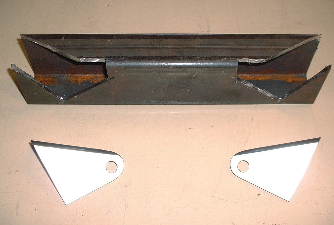
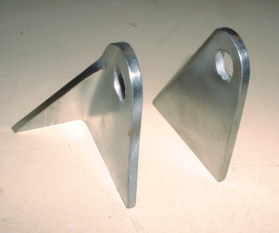
I cleaned up the burrs, sandblasted the protective coating off them, and wire-wheeled them to a nice clean finish, ready for welding and priming:
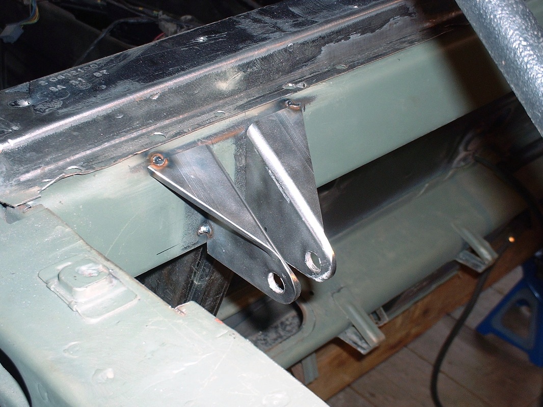
To be certain I was tacking them in the right place, I temporarily attached the shocks and double-checked the levelness and squareness then tacked them in place. Here's the driver's side just waiting for final welding.
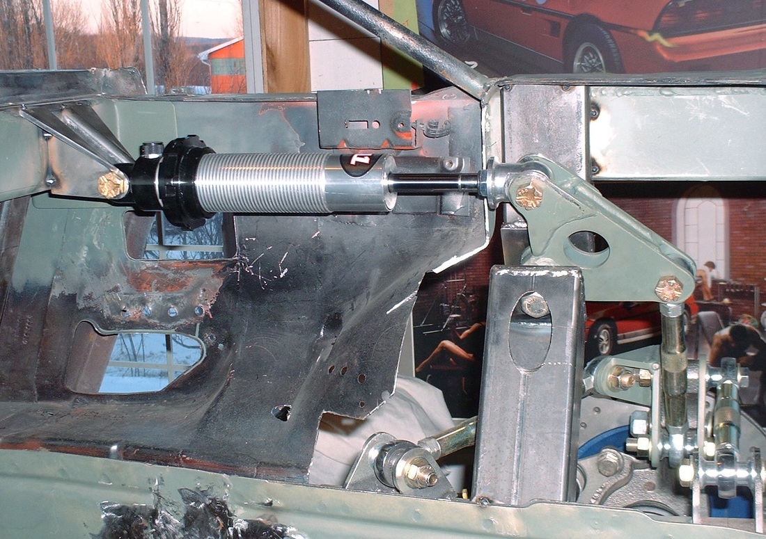
With the bell cranks and forward shock mounts finally in place, I dry-fitted the shock absorbers and was able to stand back and enjoy the view (the eagle-eyed will notice I had accidentally installed the shock backwards in this photo):

 RSS Feed
