From the get-go, it was clear that I would need custom axles. They needed to be different lengths side to side, and neither one was the same length as any stock Fiero axle. As well, the outer CV joint needed to mate with a Fiero wheel bearing assembly, and the tripot joint needed splines matching the F40 transmission at the other end. In addition to that, I wanted to incorporate a jack shaft and intermediate bearing on the passenger side to shorten up the axle and prevent it from whipping. I chose the Saturn Ion/Chevy Cobalt SS jackshaft since it was about the right length and readily available. Here was the concept with the jackshaft in pink, and the axles in red:
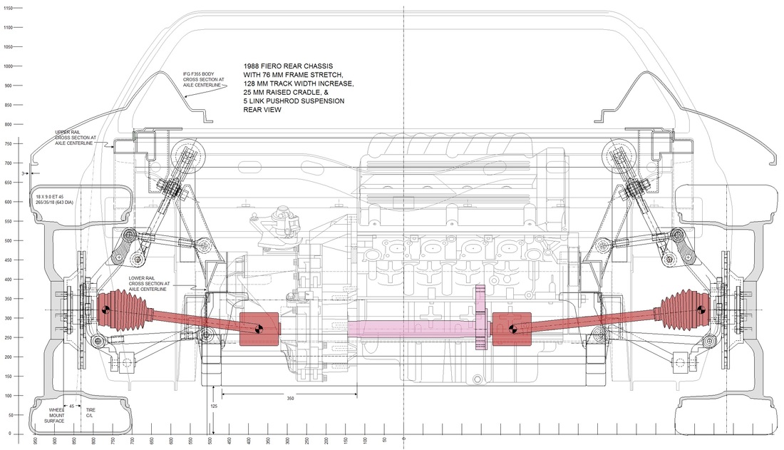
Back in post #31, I discussed how the limited space in the engine bay forced me to misalign the differential outputs with respect to the centre of the wheels. The angles are slightly different for each side since the axles aren't the same length, however at ride height they tilt approximately 7 degrees downwards towards the centre of the car and cant backwards by about 3 degrees... well within the maximum 23 degree operating range of a typical CV joint. Tripot joints actually need a minimum of a degree or two of misalignment to maintain proper lubrication.
The next step was to digitally cycle the suspension in my drawings to full jounce (green)and rebound (blue) to make sure the axles wouldn't exceed 23 degrees, nor shorten or lengthen beyond the allowable range of the tripot joint.
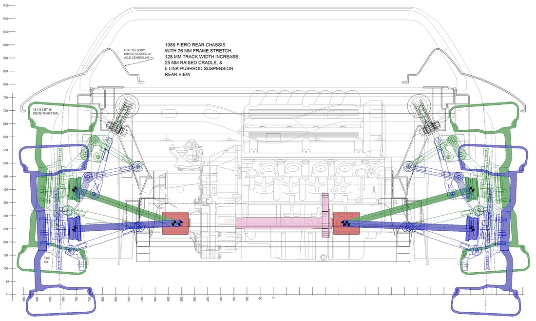
On the driver's side, I found the angles to be 18.4 and -3.3 degrees from full jounce to full rebound respectively, and the axle changed length by 22 mm's. The passenger side axle's range was from 15.3 to -2.4 degrees and changed length by 18 mm's. These are all within the safe operating range of the tripot and CV joint, especially considering the suspension will likely never reach these extremes.
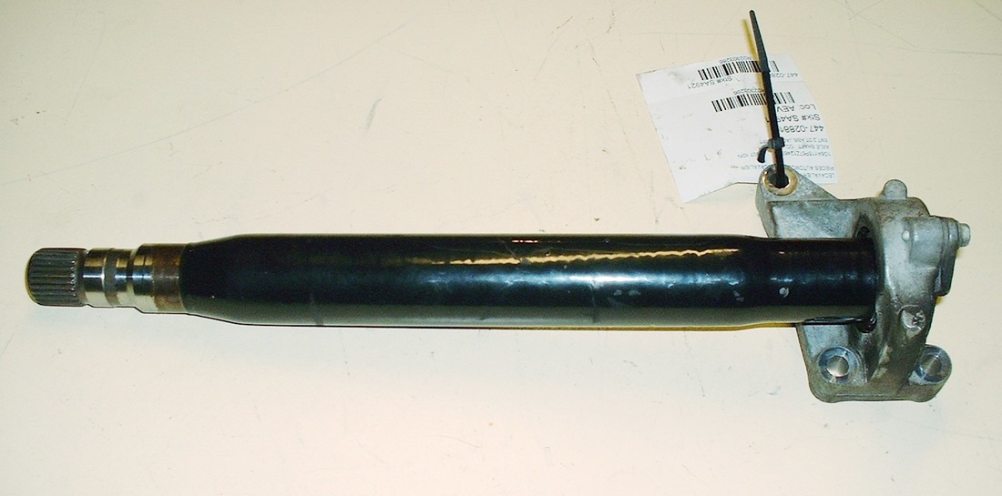
With that sorted out, I bought a 2007 Saturn Ion jackshaft and bearing assembly at a used parts dealer for $108 after taxes, and started to figure out how I'd mount it to the side of the engine:
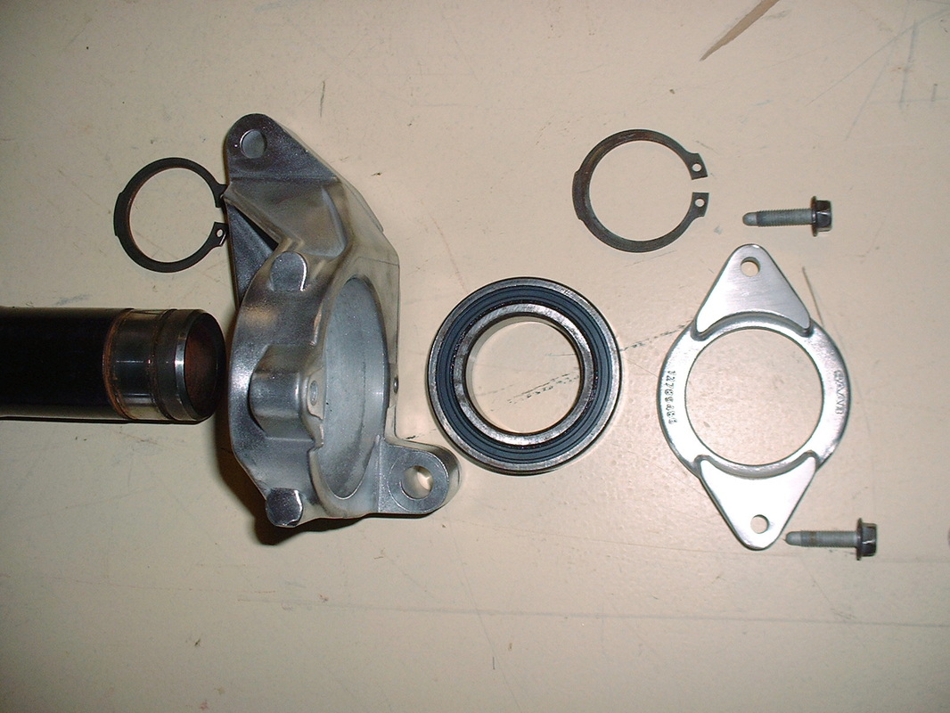
Since the Ion bearing housing didn't line up with any of the cast bosses on the side of the Northstar engine, I removed the bearing housing from the jackshaft. (Notice these parts have SAAB part numbers!)
Then I temporarily installed the bare jackshaft into the F40 differential, and installed the yellow Cadillac automatic transmission bracket onto the engine. Then ideas started to flow.
The Caddy bracket afforded a nice strong base from which to work with. It also placed the mounting holes for a new bearing housing design in a favourable orientation.
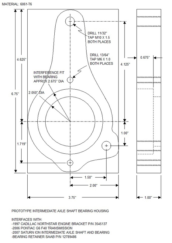
After some painstaking measurements, I designed a new bearing housing:
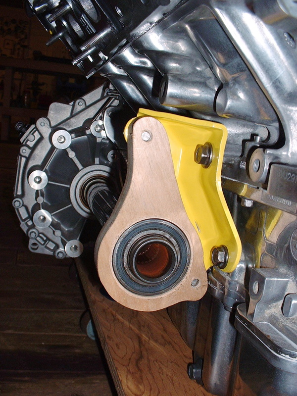
And fabricated a prototype from some hardwood to make sure I hadn't overlooked anything:
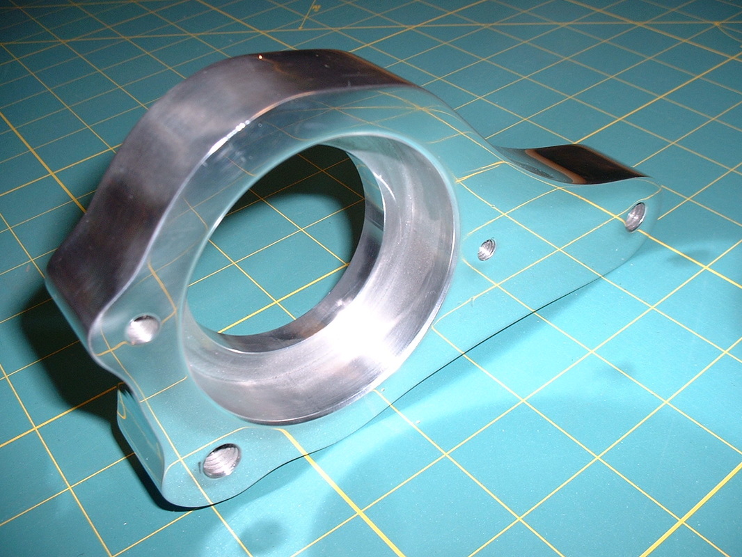
With the design finalized, I took a run out to my favourite machine shop where, for $60 ,they sold me a 7” X 3.75” X 1” block of 6061-T6 aluminium, and machined the holes for the bearing.
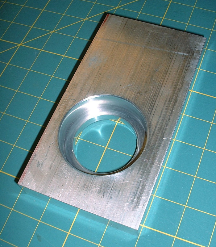
It was nice that there were some finely finished square edges on the block since that made locating the mounting holes a piece of cake. I double and triple-checked my measurements and decided it was time to make some aluminium shavings of my own:
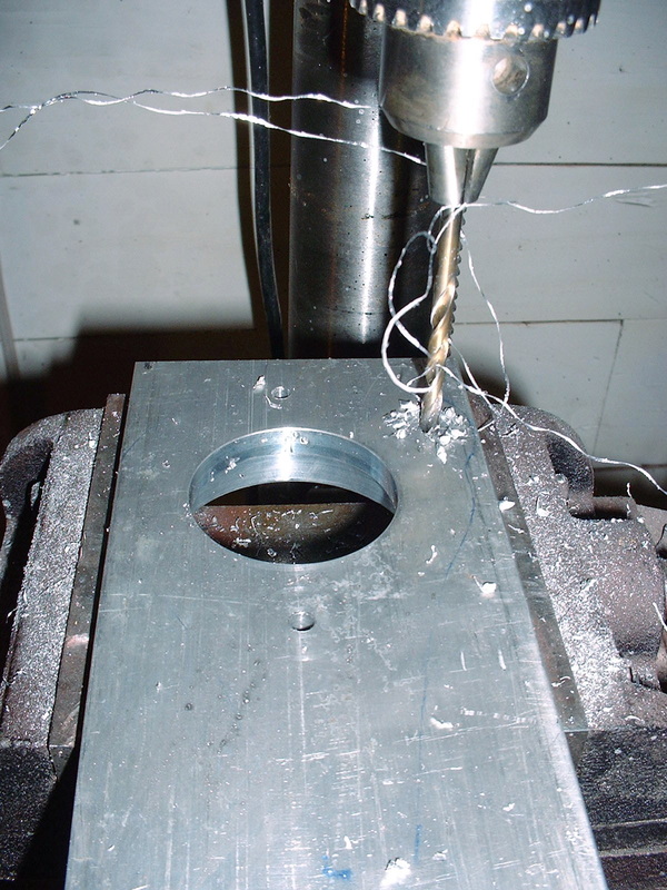
I then tapped the main mounting holes for M10 X 1.5 bolts and the little bearing retainer holes for M6 X 1.0. Then I traced the outline of the bracket onto the block and used a band saw to cut the rough shape:
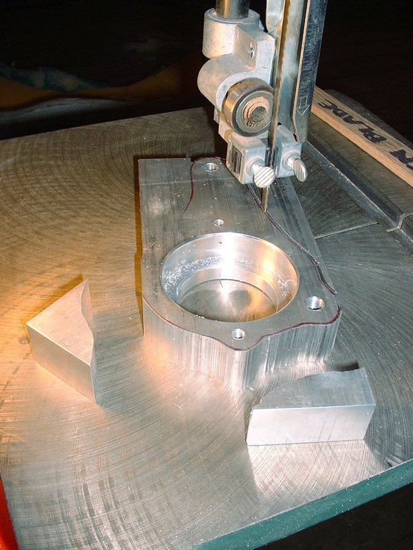
A few more operations to get rid of the scars and it wasn’t long before this thing started to look like it might actually belong on my engine. I used a 50 grit sanding drum initially on the edges, and then traded up for one with 100 grit. The drums lasted surprisingly long, in fact I only went through one of each:
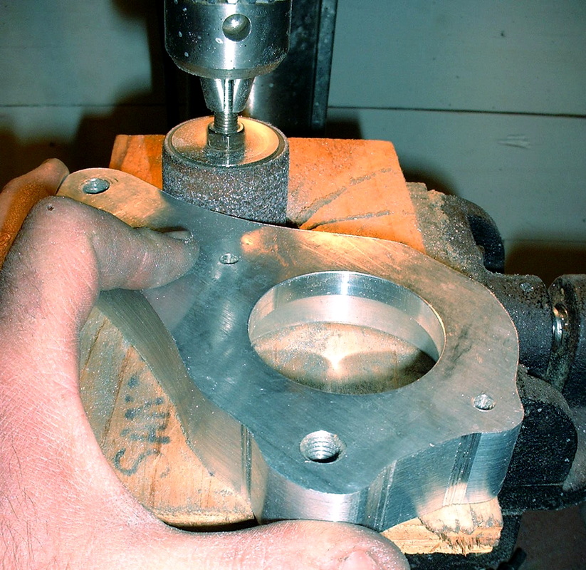
I spent about two hours of hand-sanding with some 220 grit followed up with some 320 grit and then hit the polisher with the bearing housing. I think I accidentally stumbled on cloaking technology! Check it out:
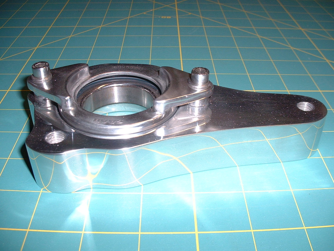
And here it is with the Ion bearing and retainer bolted on and ready for installation:
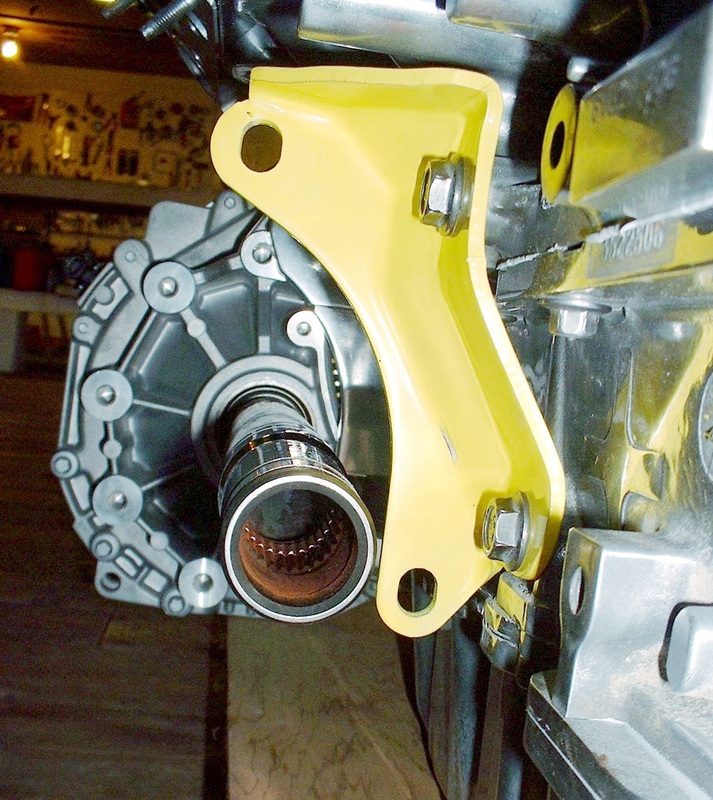
I roughened up the powder coating on the jackshaft with a Scotchbrite pad, undercoated it with some white paint, then hit it up with John Deere yellow. Once it was dry, I was able to press it into the bearing, and mock up both pieces onto the engine bracket:
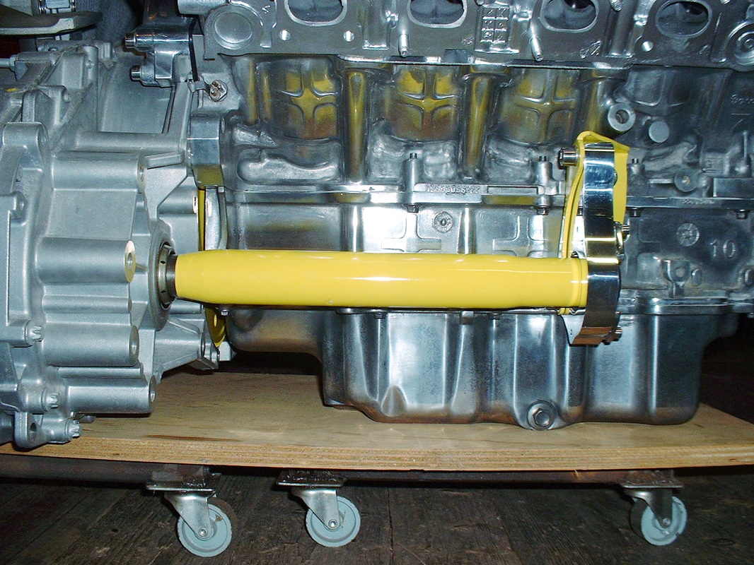
Initially, I found that the axle didn’t turn very freely, so I removed it and elongated the holes in the yellow bracket for some adjustability. I managed to find the sweet spot and tightened it up.
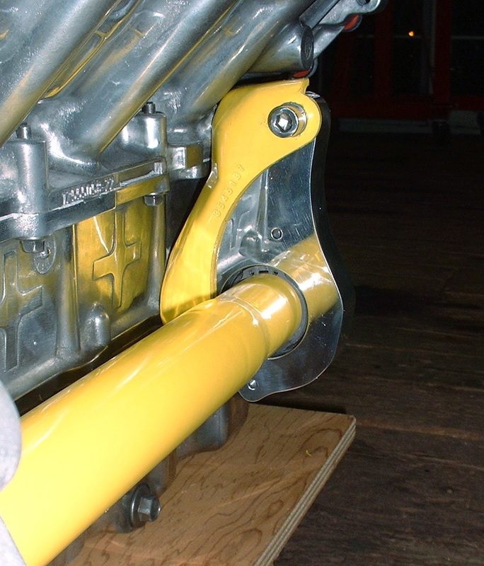
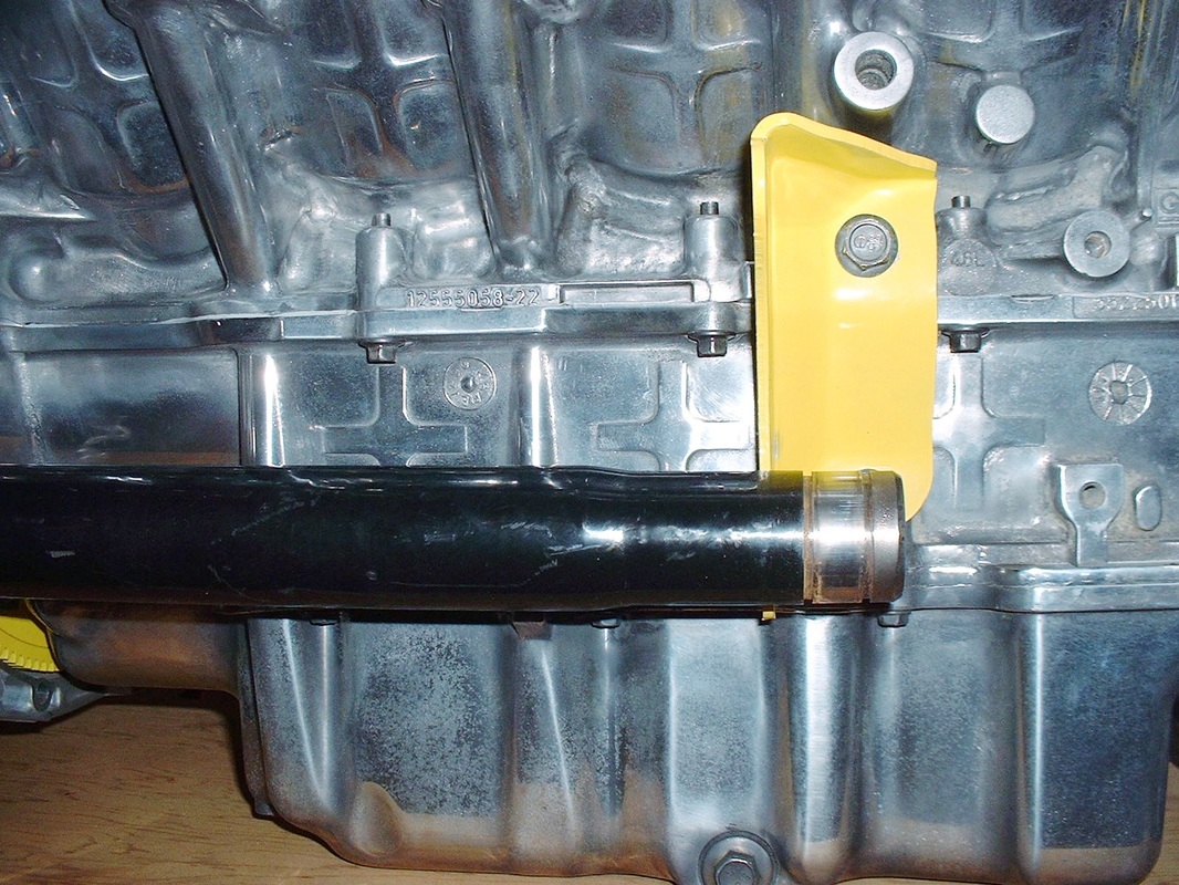
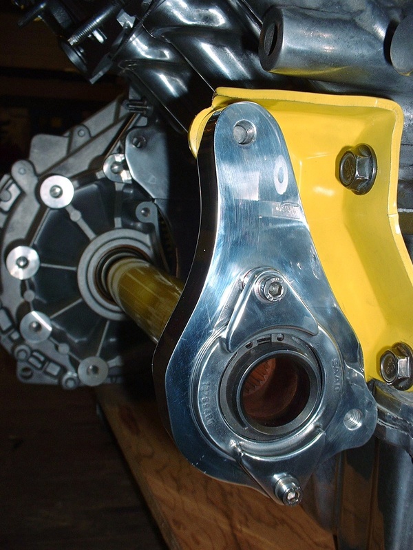
Finally, here’s the view from the wheel-side of things.

 RSS Feed
