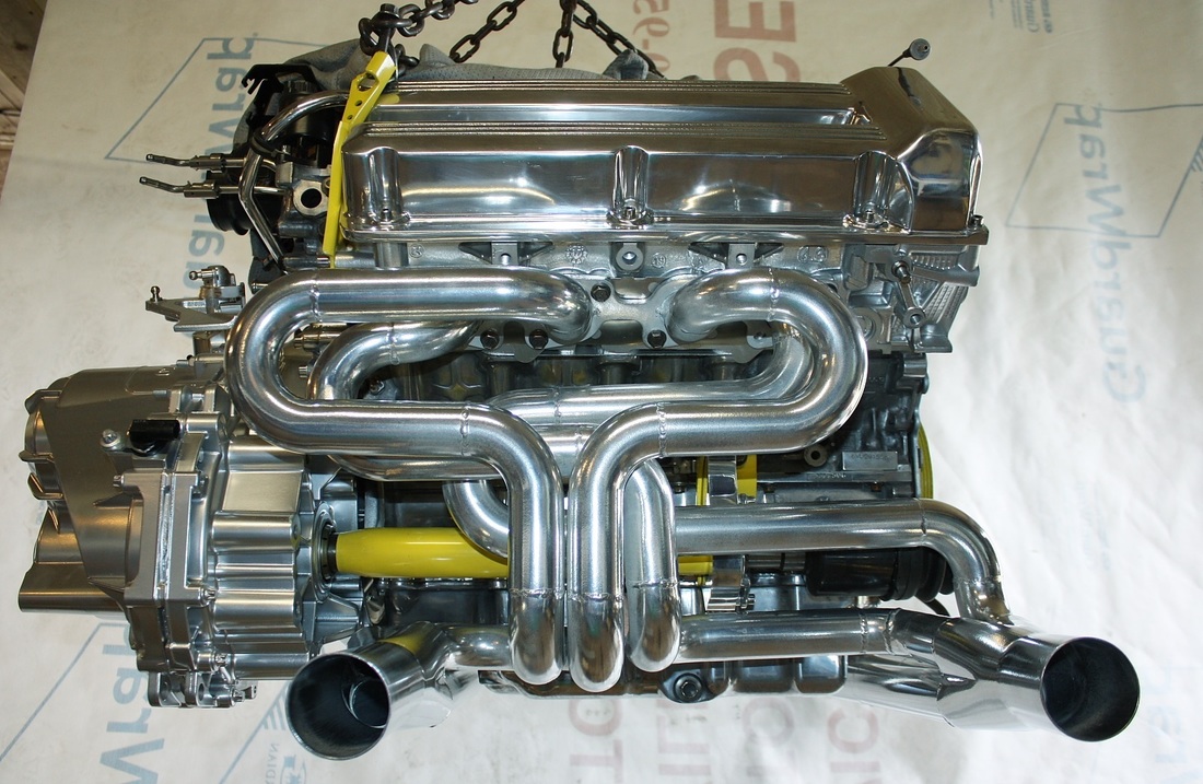
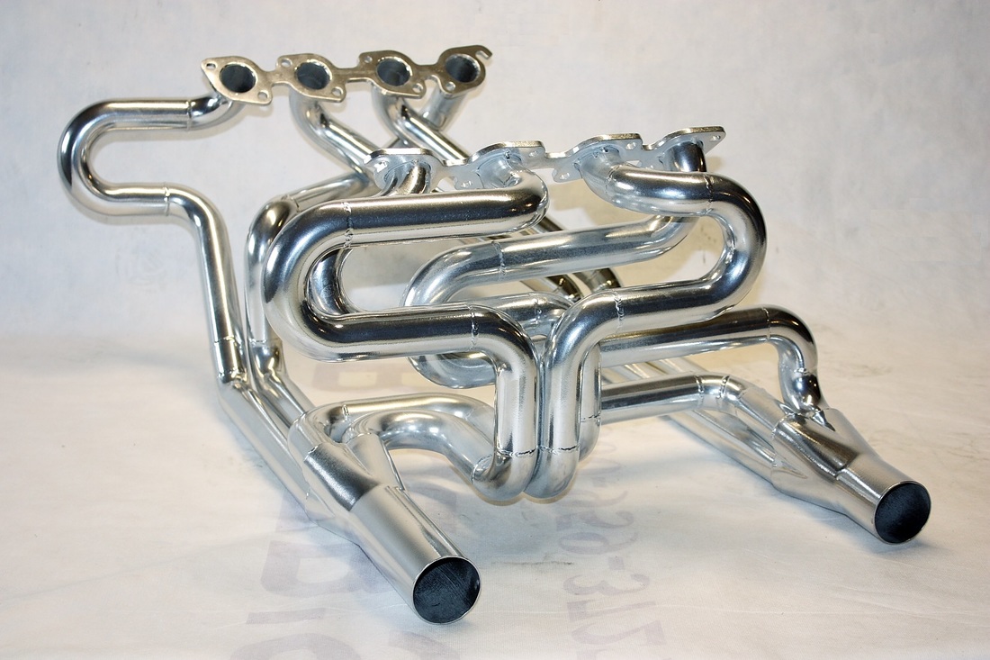
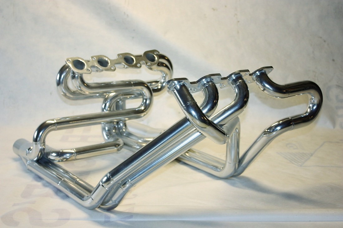
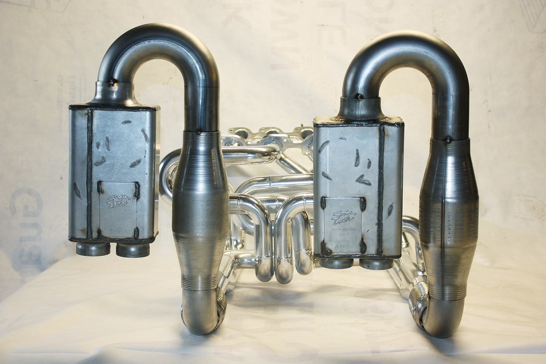
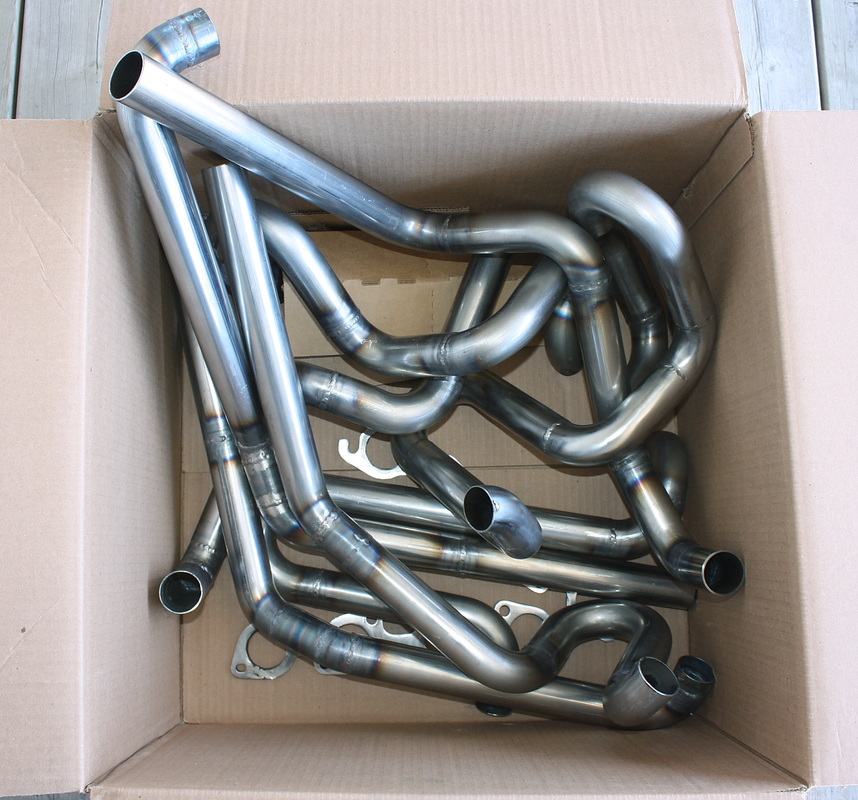
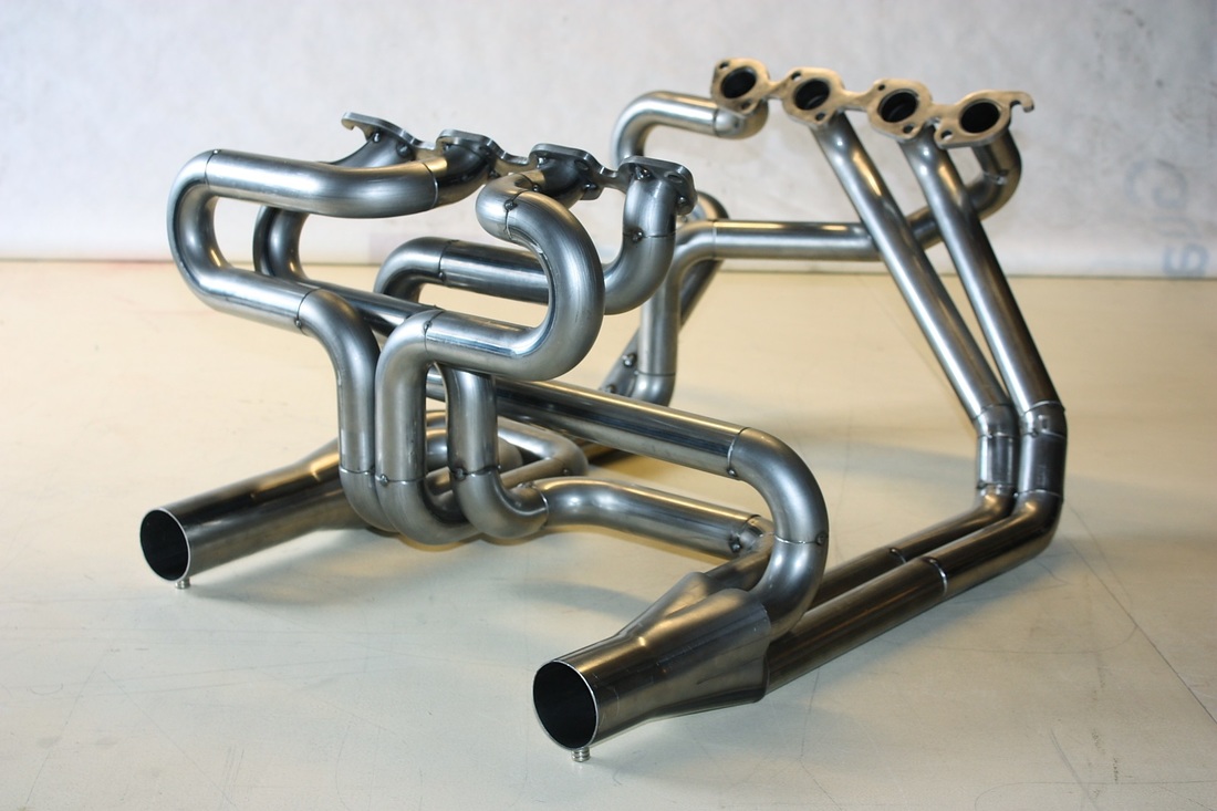
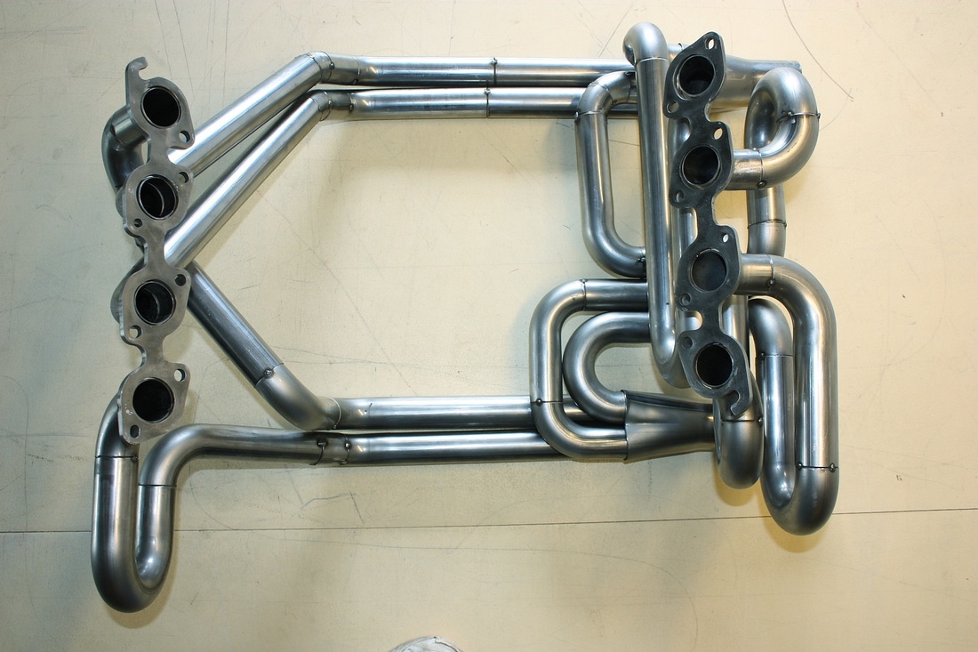
With the headers back home I finally had all the pieces of the puzzle to begin rebuilding the cradle assembly for the last time. The first thing I did was reinstall the headers and snap a few final pics:
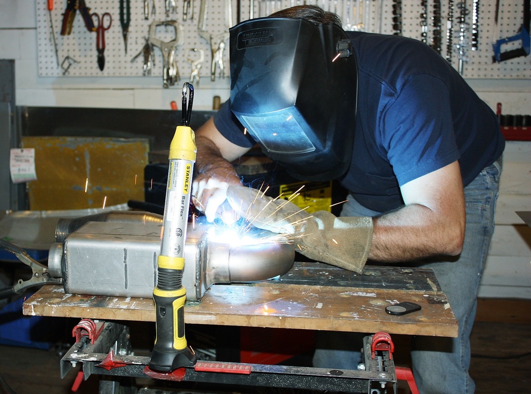
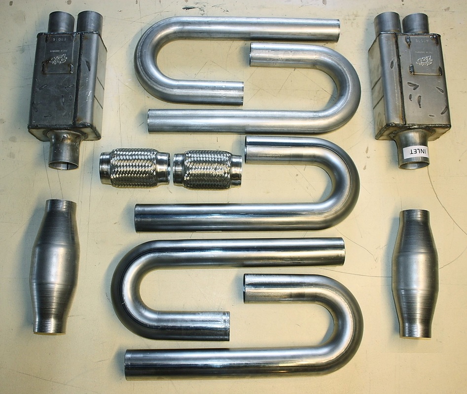
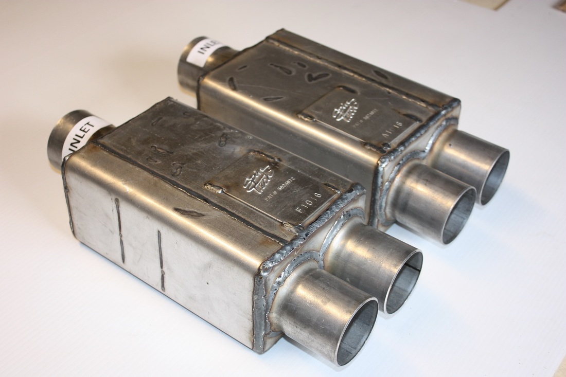
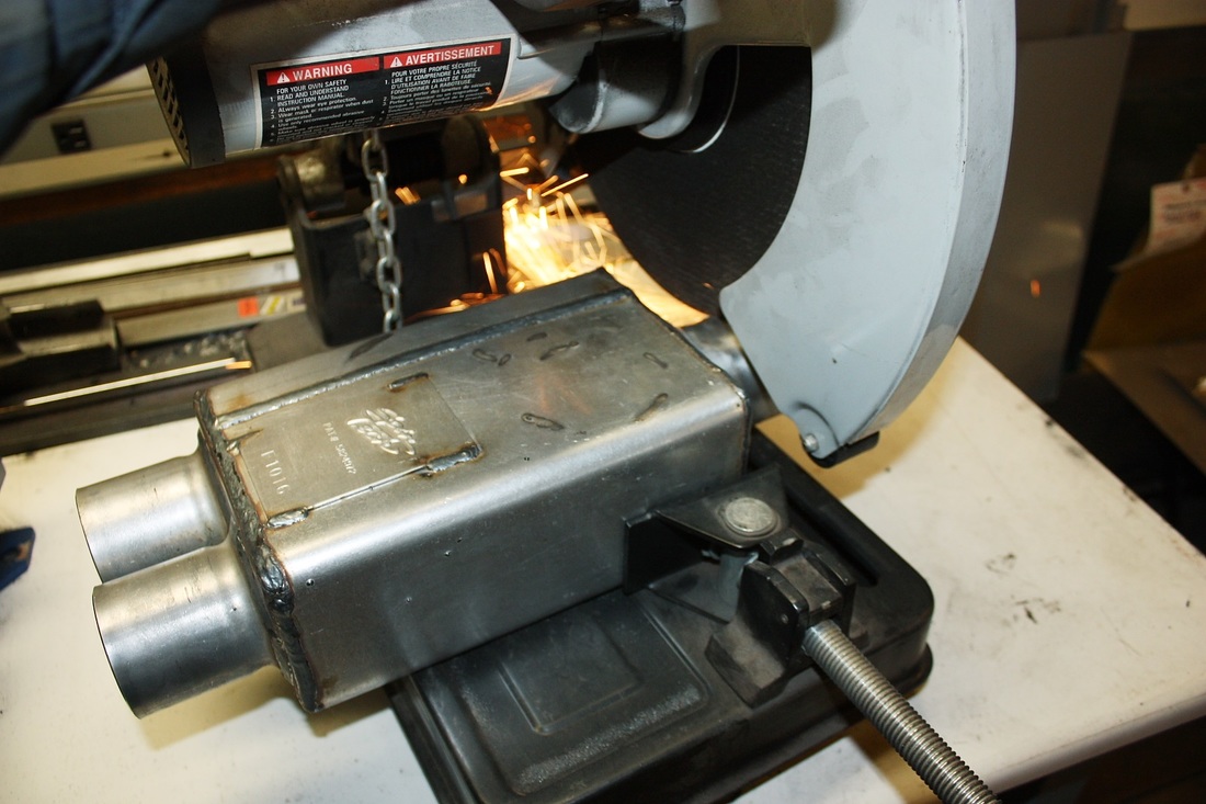
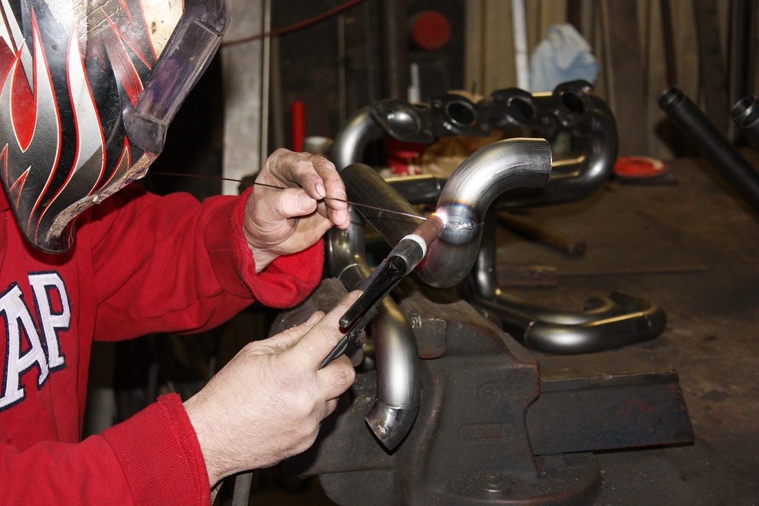
Then I got busy finalizing all the tack-welded cat-back components. Here I'm welding a Spin Tech muffler to the U-bend leading from the Magnaflow converter:
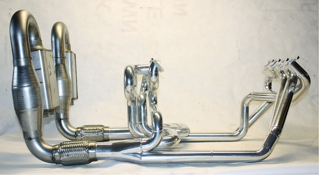
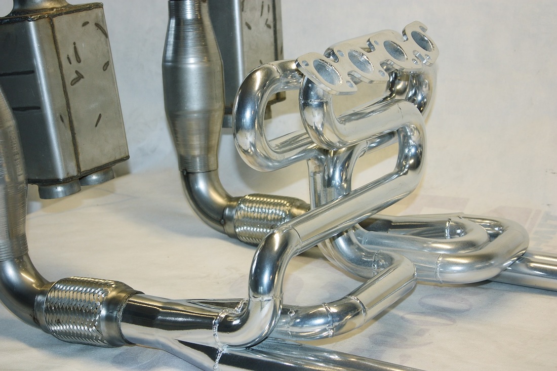
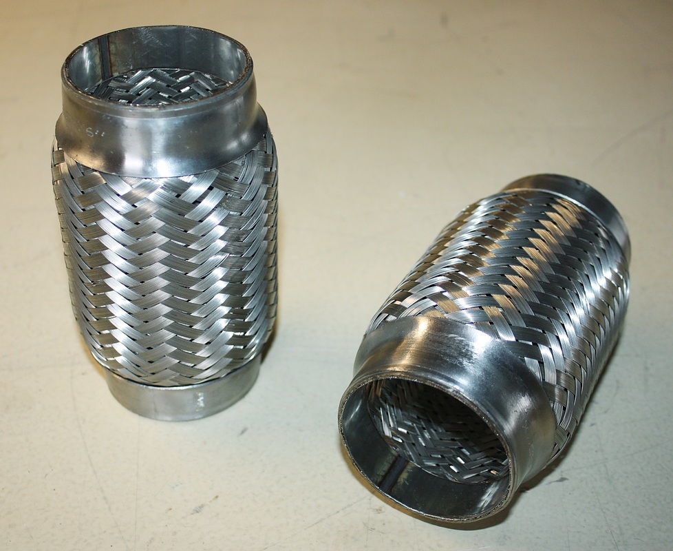
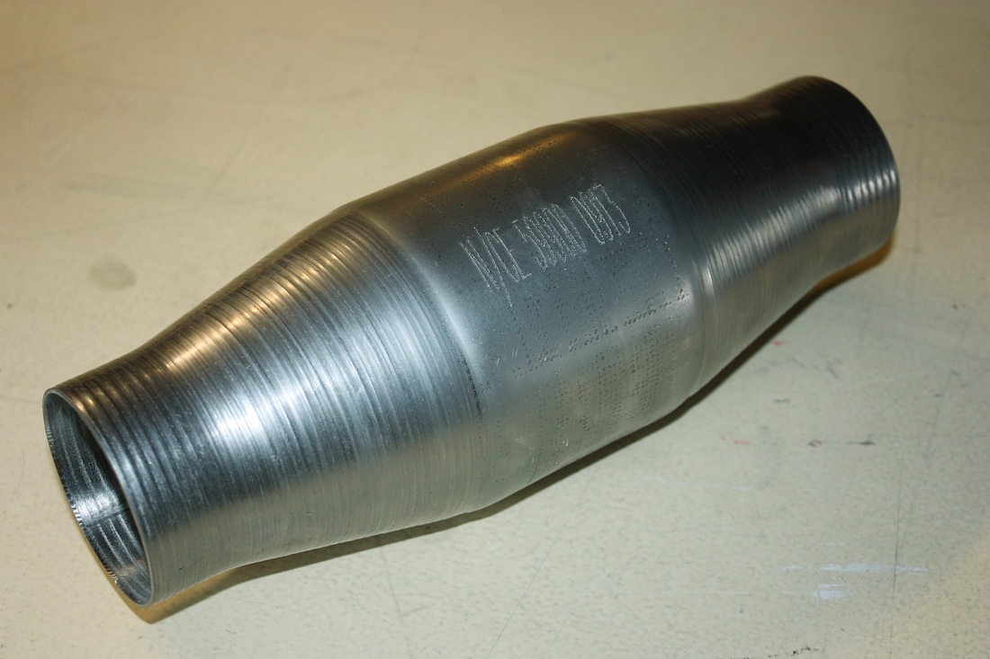
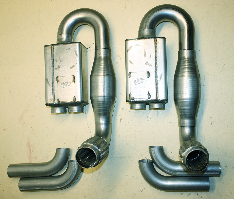
Next up was to complete the 90 degree elbows and flex joints connecting the collectors to the catalytic converters. First I welded the flex joints to the 2.5" diameter elbows, and then began planning the oxygen sensor fittings:
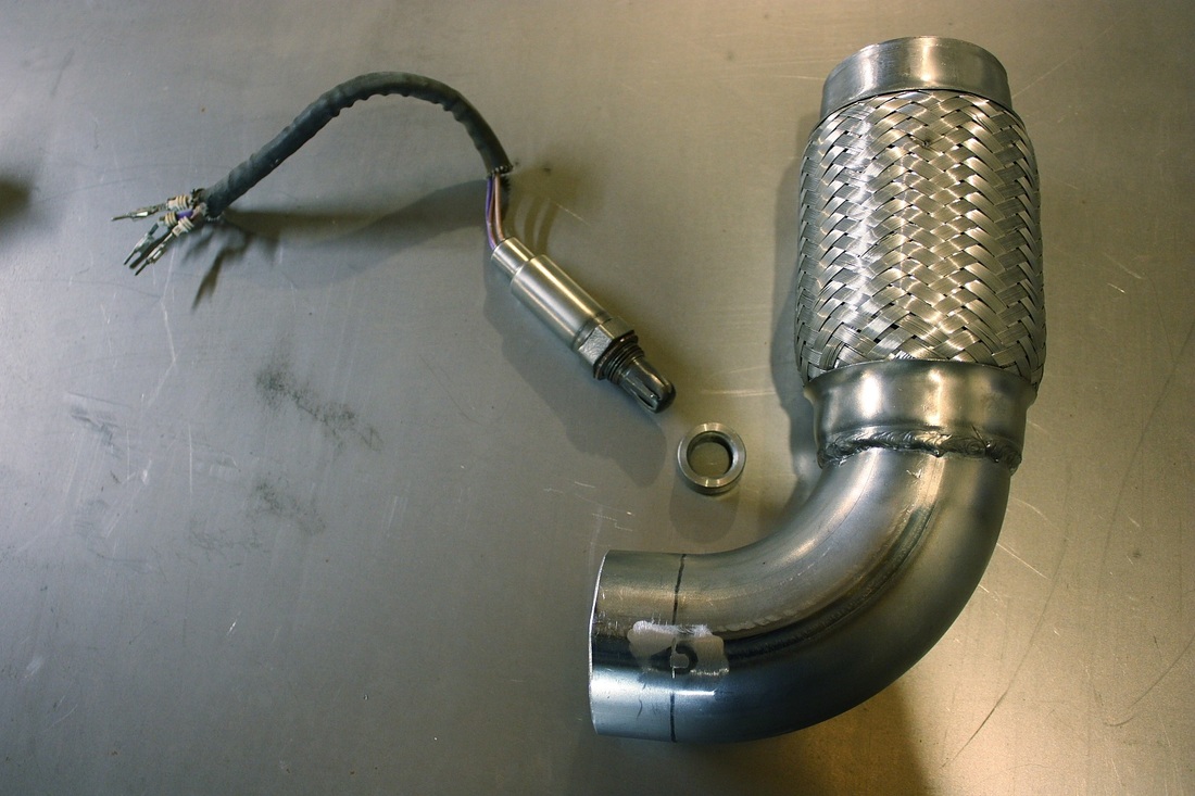
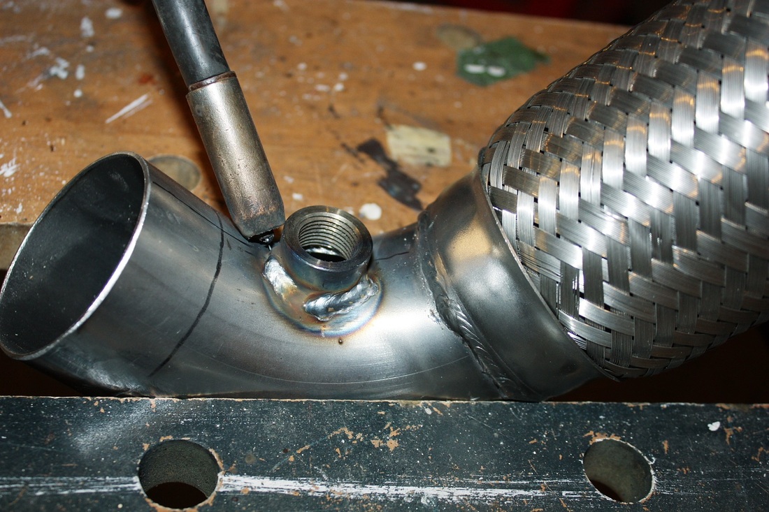
I wanted to install a total of four O2 sensor bungs: two for the PCM, and two for wideband O2 sensors for tuning the fuel map later on. The ideal placement for the bungs would've been in the collectors, however I simply didn't have the room, so the next best location was about 8" downstream, just past the flex joints. I marked the centrelines of the elbows and used a hole saw to cut into the pipes:
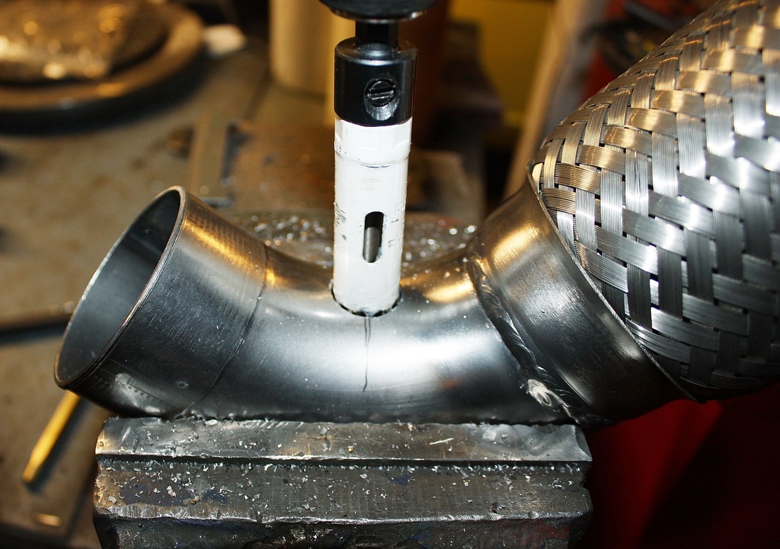
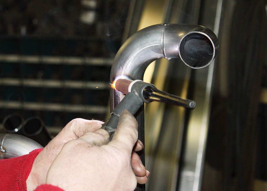
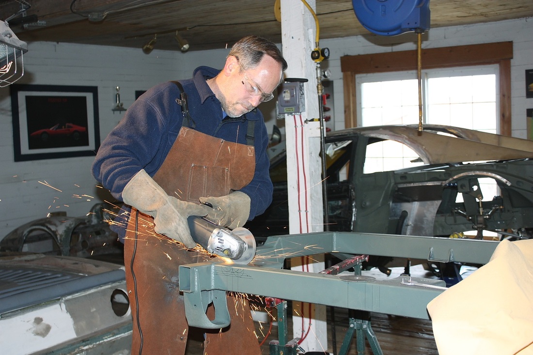
Then I ground the base of the sensor bungs to fit the contours of the pipes and welded the bungs into place with my gas MIG welder:
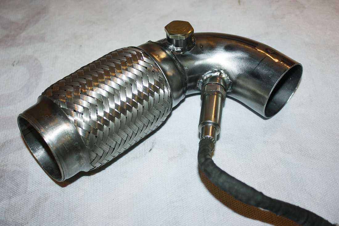
Here's one of the elbows with both fittings welded in place and the OEM oxygen sensor screwed into one of the ports, while the other is capped off with a plug:
The last step was to weld the completed flex joints and elbows to the ends of the collectors, with the elbows pointing upwards. I didn't get any photos of that.
The next phase was to get the engine and transmission installed back onto the cradle, but up until this point, the cradle had only been primed with a self-etching primer. It had to be painted before the engine/trans could be installed, so I bought some 2K epoxy primer available in special spray cans at NAPA, and sprayed the cradle:
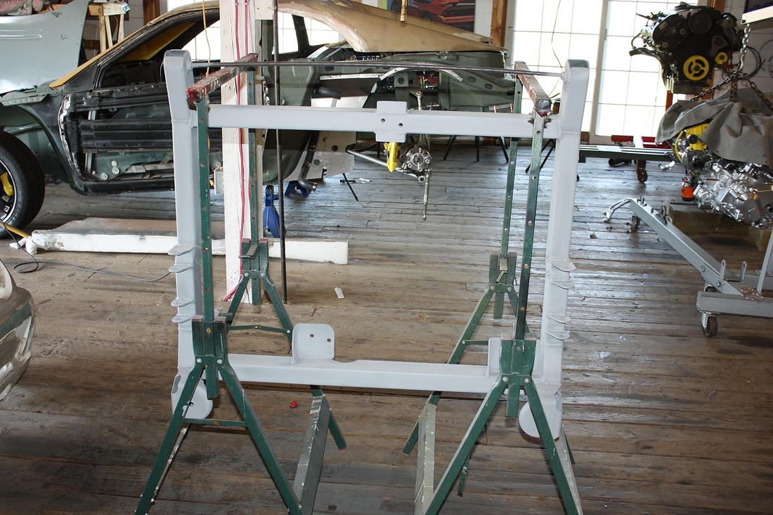
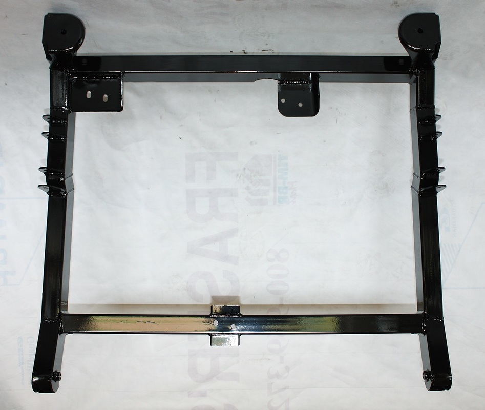
Once it had hardened, I painted the cradle gloss black. I struggled with the colour choice but in the end I decided that the cradle would only be seen if the car was suspended on a hoist. Since I plan to paint the engine bay body colour (yellow), I decided black would contrast nicely against the backdrop of the bay. Here it is drying:
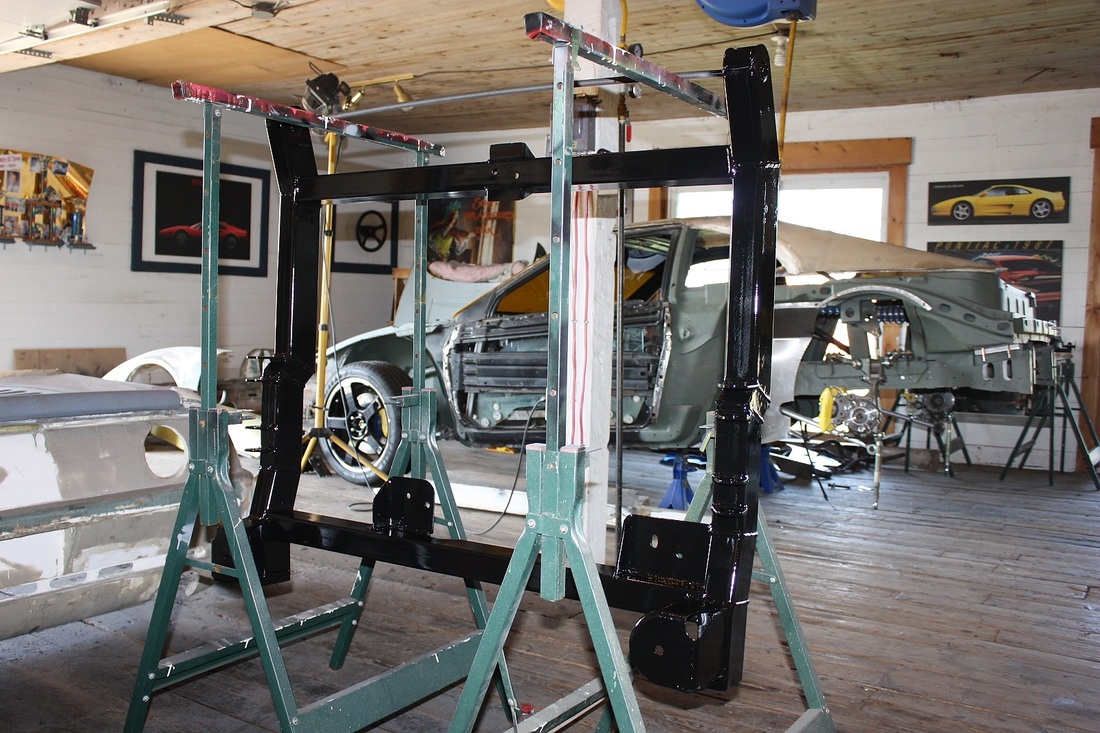
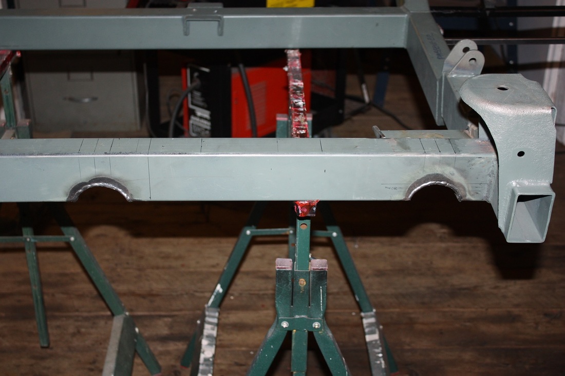
And here it is one final time in its bare form:
As I write this, I find it odd that what I did next was to install the cradle onto the engine/transmission combo. Anyone familiar with a typical Fiero installation, the engine/transmission combo is usually lowered onto the cradle, not vice versa.
The difference here was that my new one-piece headers had to be installed on the engine first, in order to fit. But once installed, the collector outlets needed to pass under the rear cradle cross member, so lowering the engine/trans onto the cradle would not have worked.
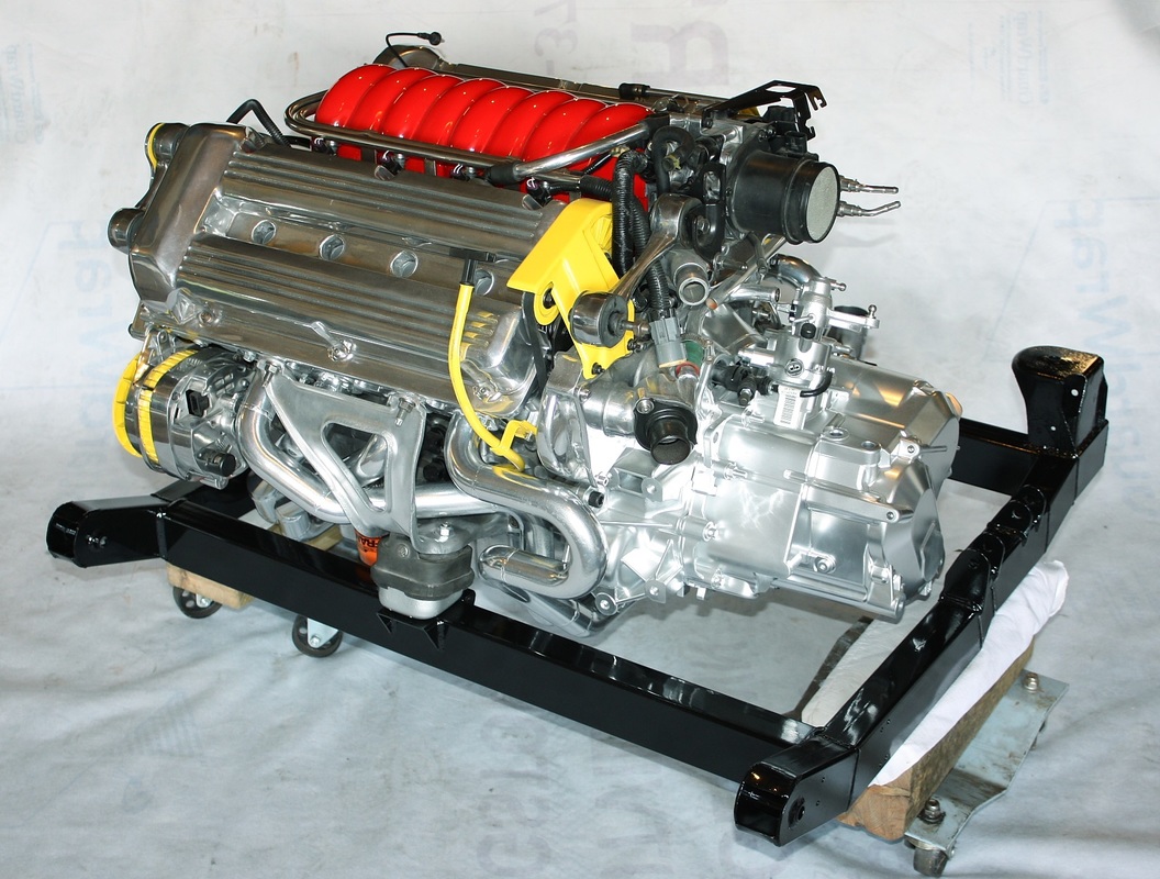
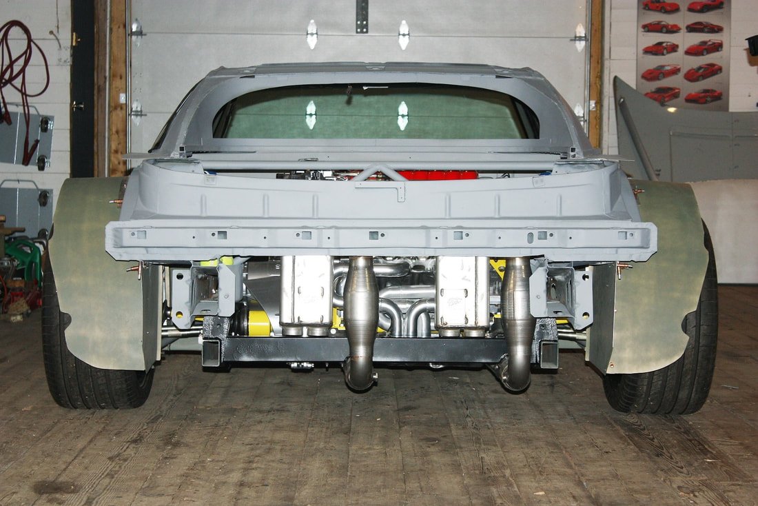
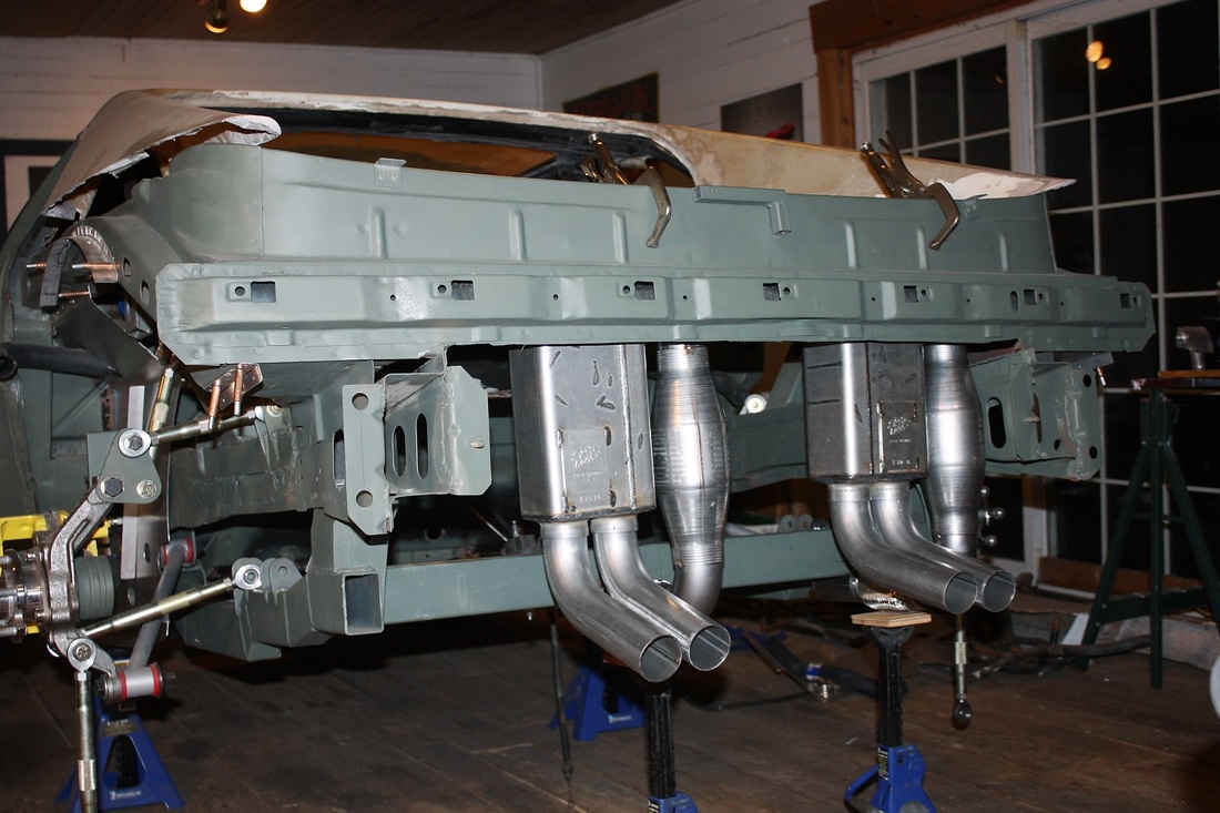
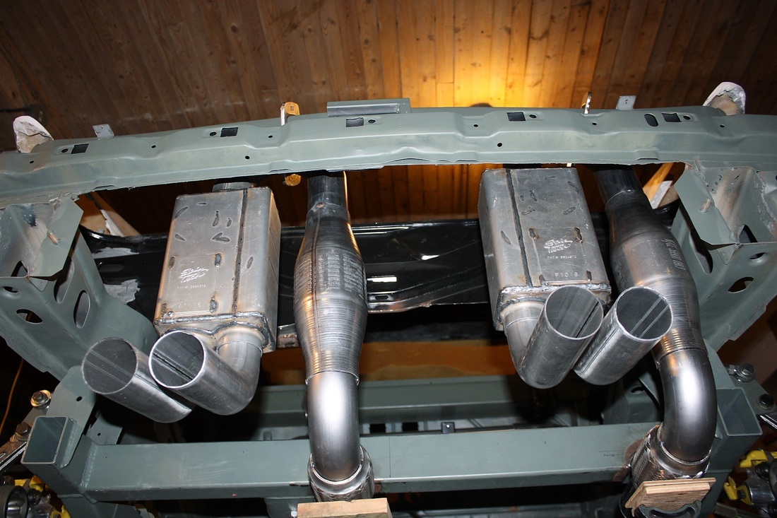
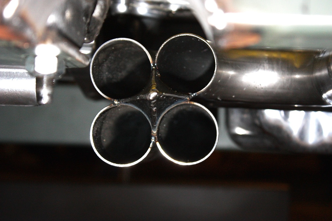
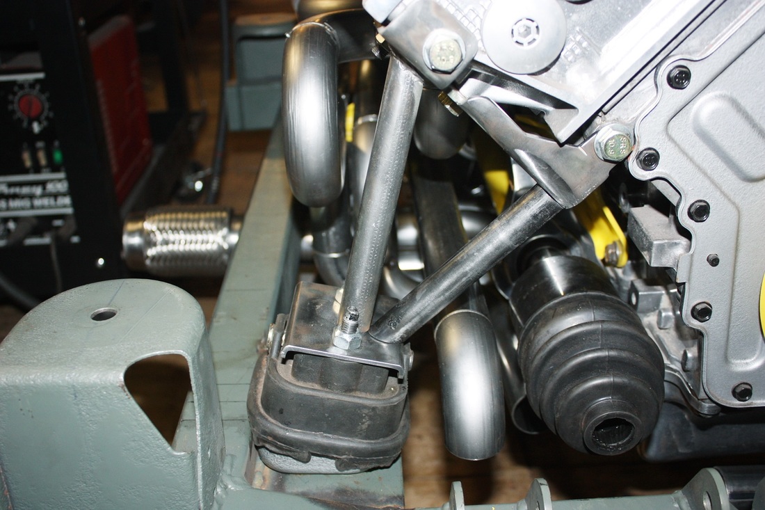
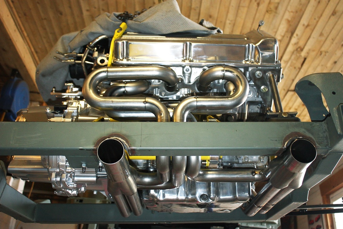
Instead, I had to suspend the engine/trans from a hoist, thread the cradle onto the collectors from the back, and hold the cradle in place while the three mounts and mounting brackets were installed in a very specific order. All this while trying desperately not to scratch the paint on the cradle, nor the ceramic on the headers. Needless to say I didn't get a chance to take any photos while doing this gravity defying feat. But here's the final assembly from the rear:
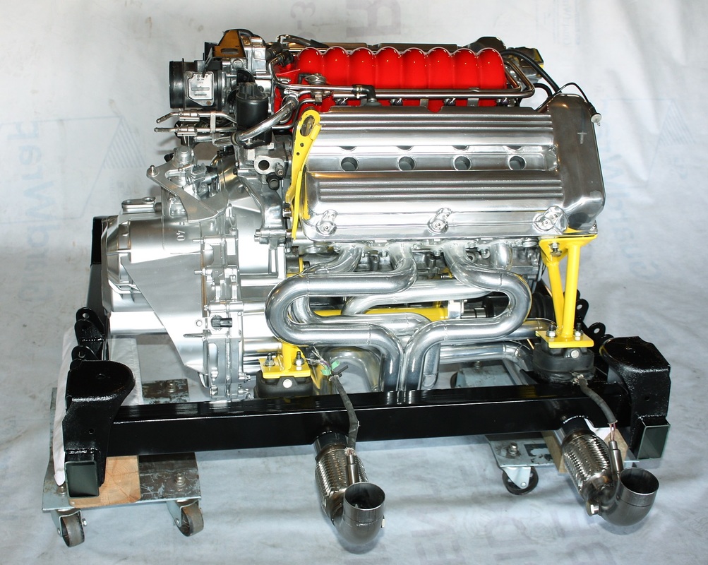
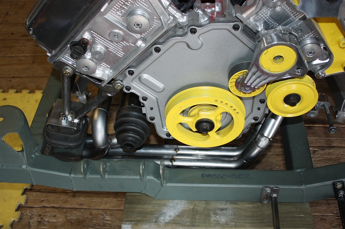
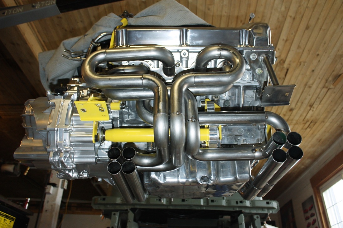
I took a bunch of photos while walking clockwise around the cradle assembly. Here's the LH rear quarter view:
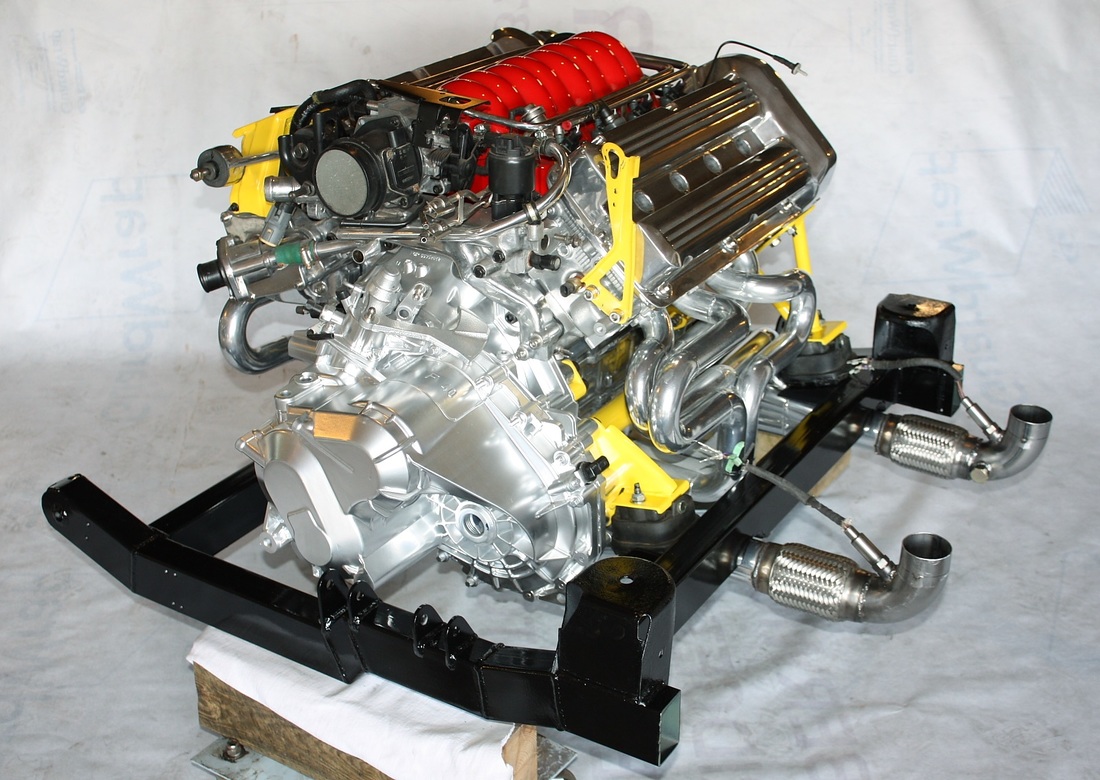
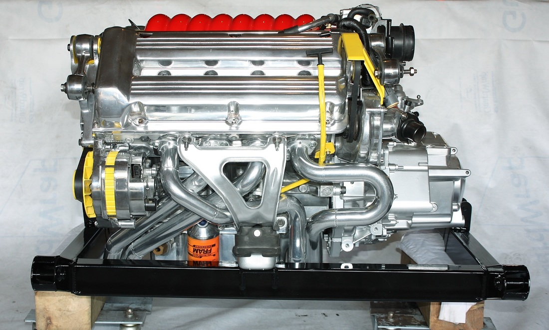
Left hand side view:
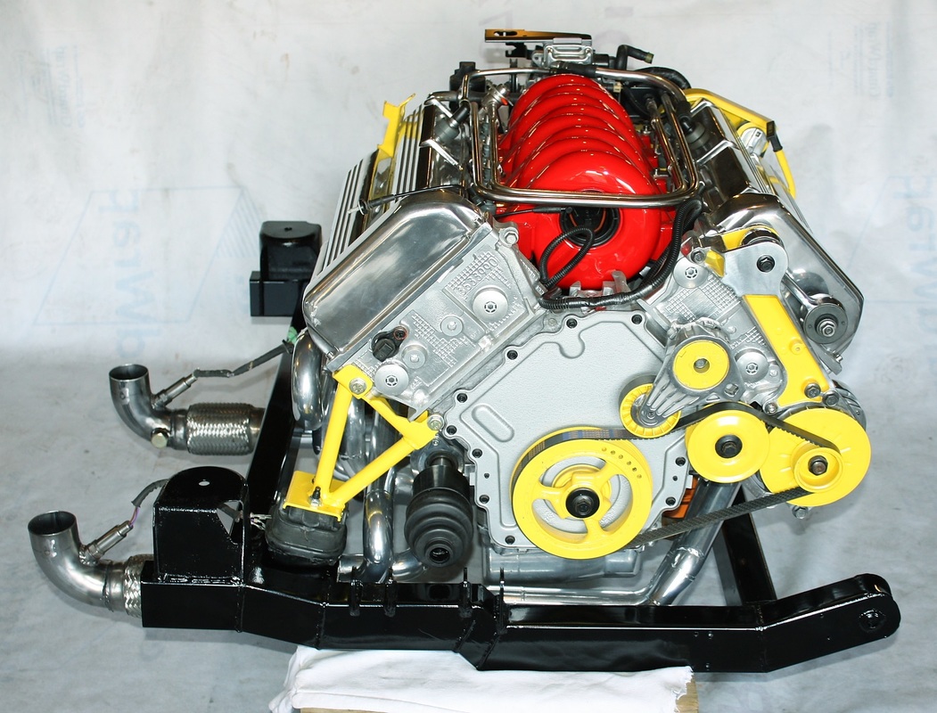
Front LH quarter view:
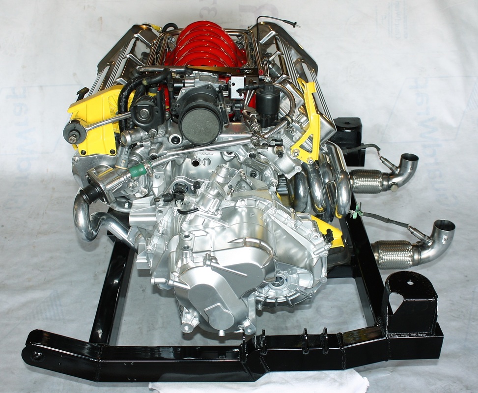
Front View:
RH view:
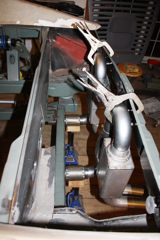
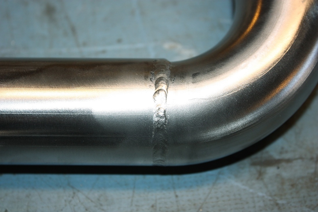
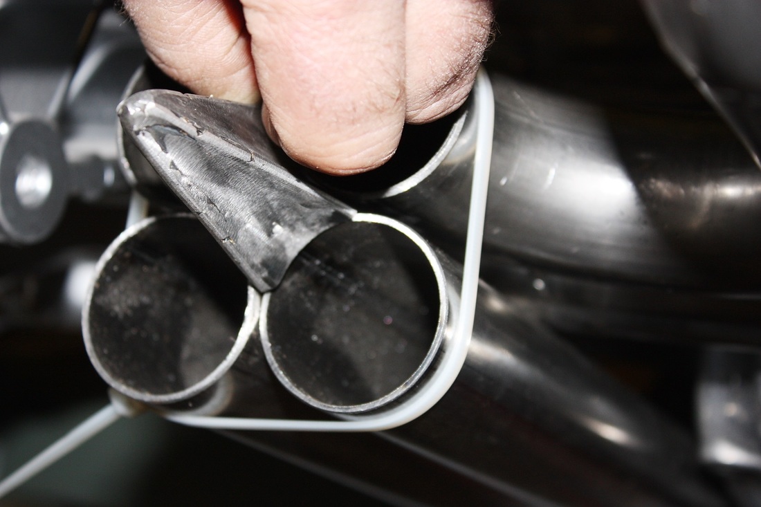
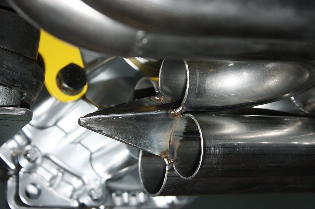
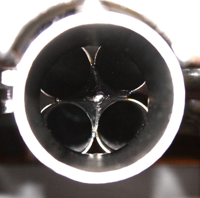
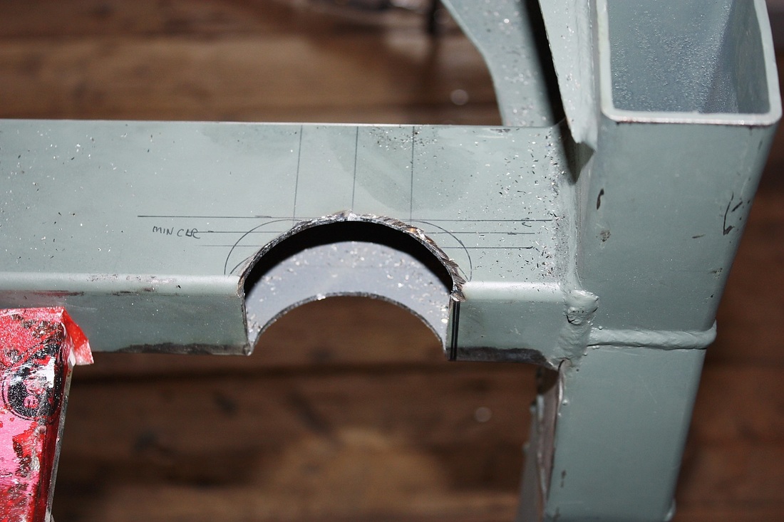
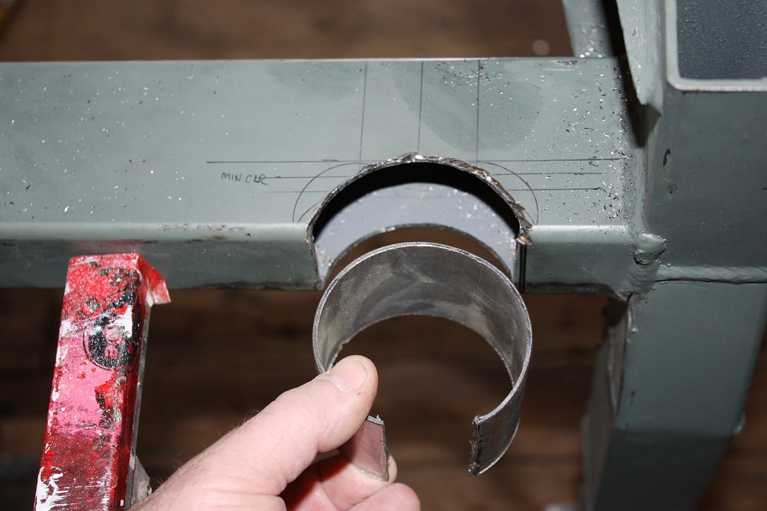
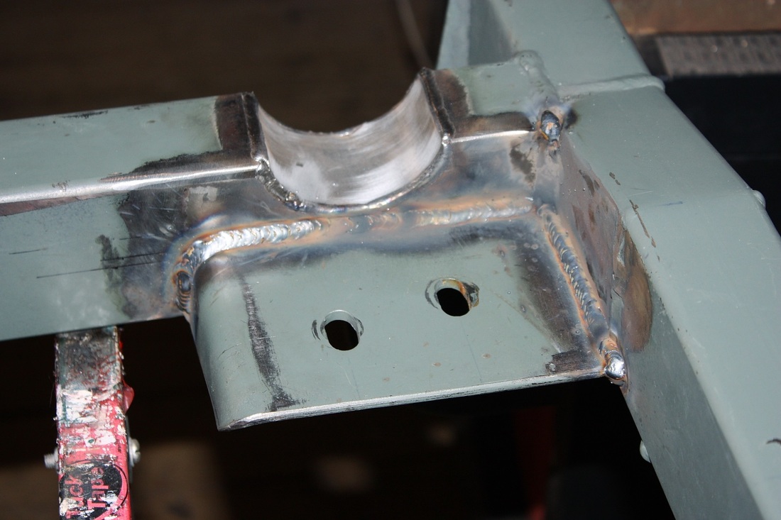
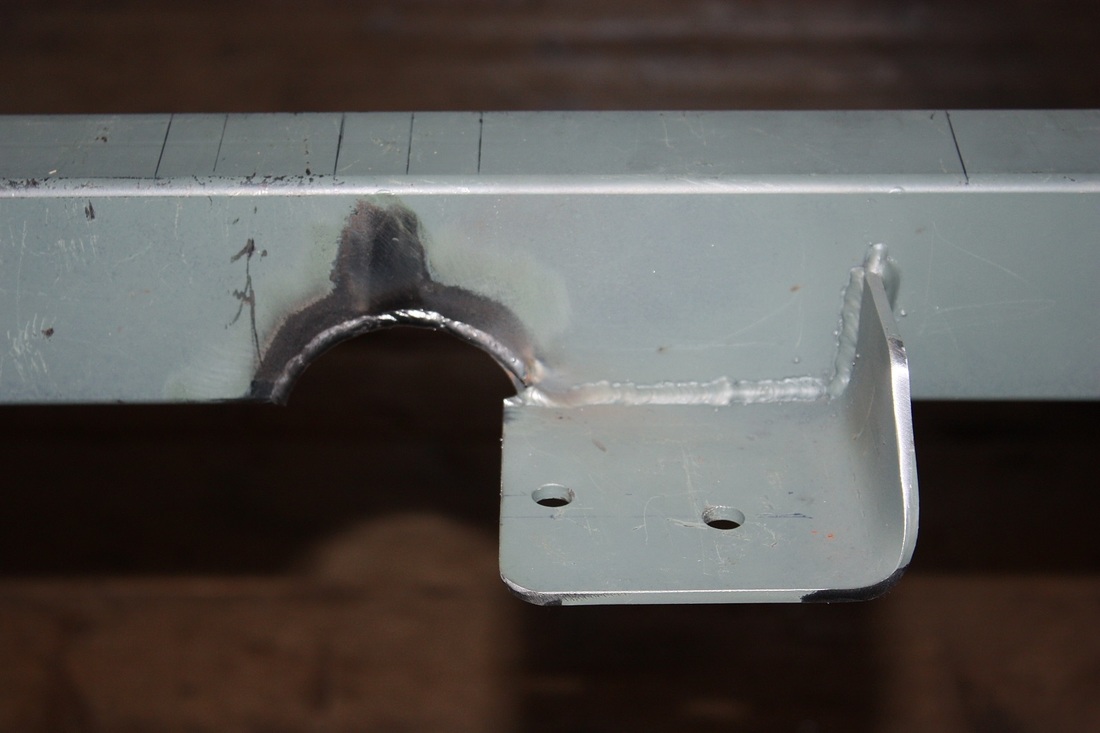
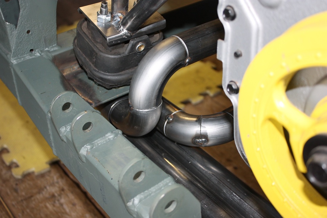
And finally a close up of a flex joint. If you look closely, you'll see the clearance between the end of the collector and the underside of the rear cradle cross member:
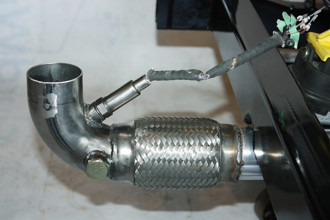
The rounded notch gives about 3/4" clearance for drivetrain movement. It isn't much, but the only time the engine will rotate forward and result in the clearance getting smaller will be during compression braking. That 3/4" gap should be plenty. Under acceleration, the gap will increase as the engine rocks backwards.
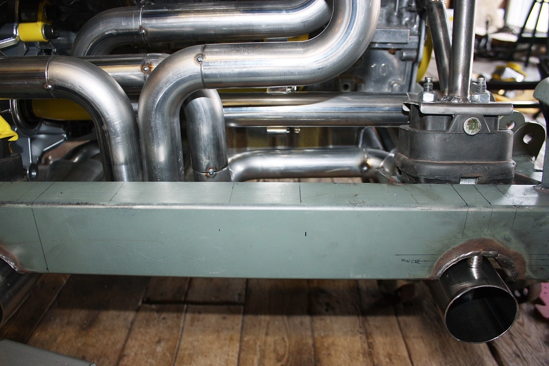
Finally, here's view of what the reinstalled system will look like, albeit without the rear bumper bar, and without the quad tailpipes.


 RSS Feed
