With the extended windshield frame and the wiper system sorted out, only the heating and ventilation system interference was left to solve. I resorted to 2D drawings of the system in cross section to get a better grip on how to solve the issue. I started by drawing the stock layout of the metal cowl, windshield, and HVAC unit:
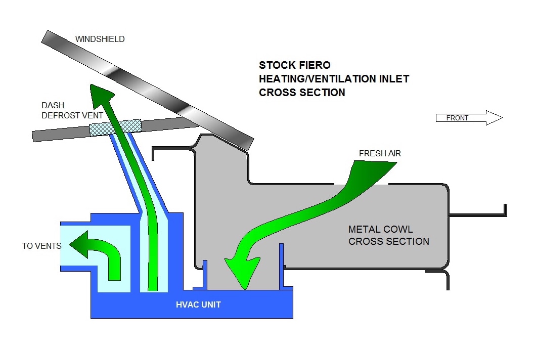
Outside air is drawn into the unit through a grill at the base of the windshield. I've left out the grill for simplicity and shown only one of two large holes in the underlying metal cowl (grey area). I've also left out the inner workings of the HVAC unit to keep things simple for now.
There are two main problems that the extended windshield create with respect to the HVAC system. The first is that the stock outlet for the defroster ends up being so far away from the base of the windshield that some people have found it doesn't adequately do its job (see left-most yellow arrow below). I'll deal with this issue in a separate post since the other problem is more important.
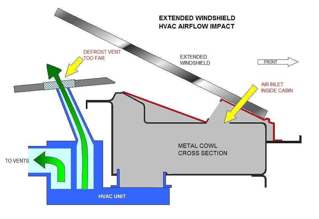
The other problem is that the windshield, along with the new lower windshield frame (red lines in above pic), cover up the air inlet holes in the metal cowl. The new windshield essentially reaches so far ahead that the fresh air inlets end up inside the cabin! One bonus was that it would do away with the need for a fresh air/recirc button, but the fresh air option is a "must" knowing some of my farmer friends will want rides.
Obviously I would need to relocate the inlet. It didn't take too long to figure out where it should and could go, and how to do it:
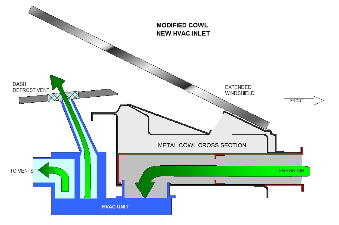
In the drawing above, I made a hole in the forward vertical wall of the cowl, added a snorkel of sorts, then divided the grey cowl chamber into upper and lower halves with a sheet metal divider (red lines). The lower half becomes the new HVAC air inlet duct, and the new sheet metal divider seals the inside of the cabin off, while still leaving options open for a new defroster at the base of the windshield.
From the top view, the left to right location of the new cowl inlet was determined by the Sky/Solstice inlet location. It fortunately fell in an area where it's unencumbered by things like the wipers, brake hardware, etc. The only concession is that it's offset from the central location of the HVAC unit inlet:
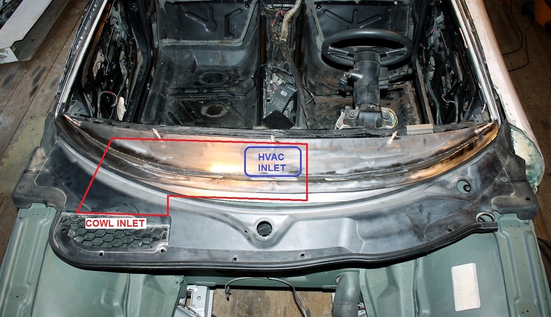
With my plan in hand, I set out for the shop and marked where I needed to make a hole in the front cowl:
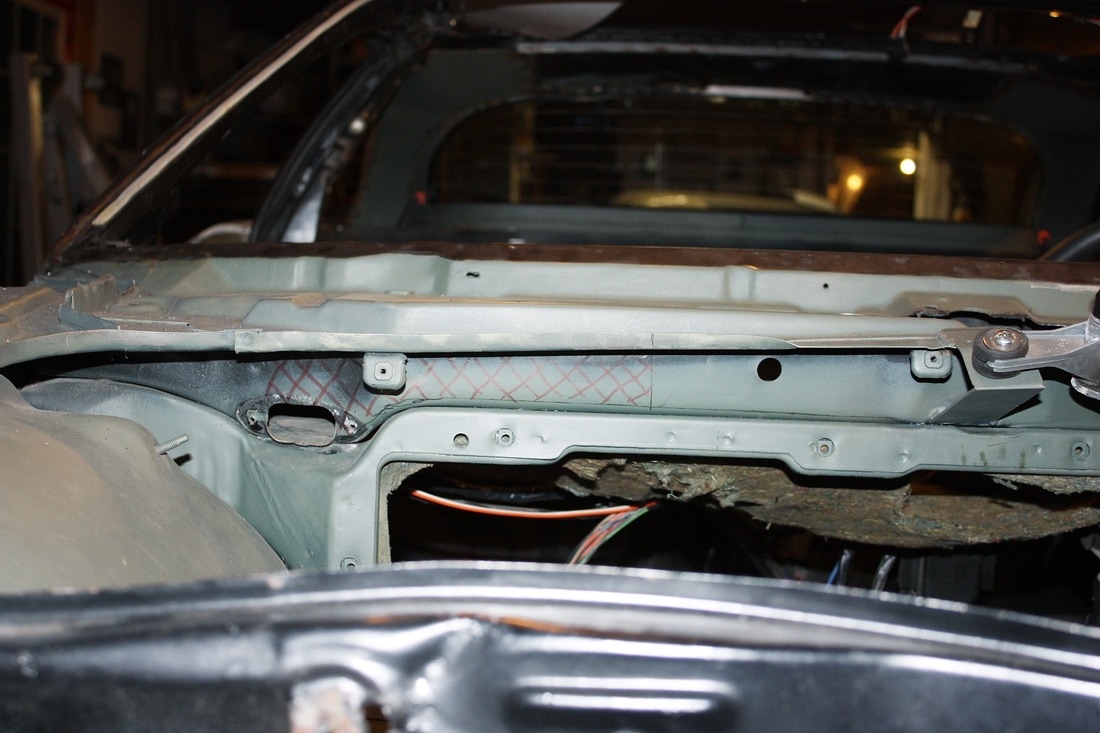
Cutting out the sheet metal was a breeze with a thin cut-off wheel in my angle grinder, though I did need to dress the hole a bit afterwards:
I wasn't overly concerned about choking the airflow with new passages, but I did few cross sectional area calculations just the same. Since the HVAC fan shroud measures 132 sq-cm, then as long as the cross sectional area of my new duct work fell within the same range, it should still move about the same volume of air. My new cowl hole measures 111 sq-cm.
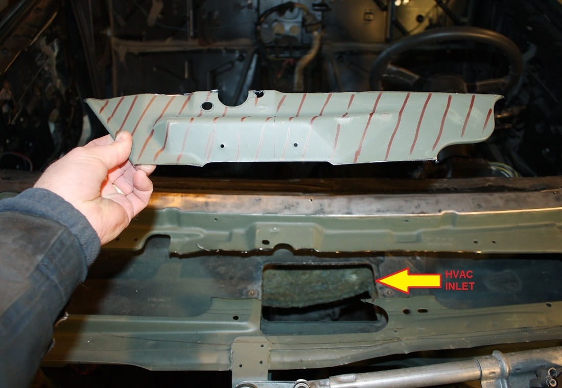
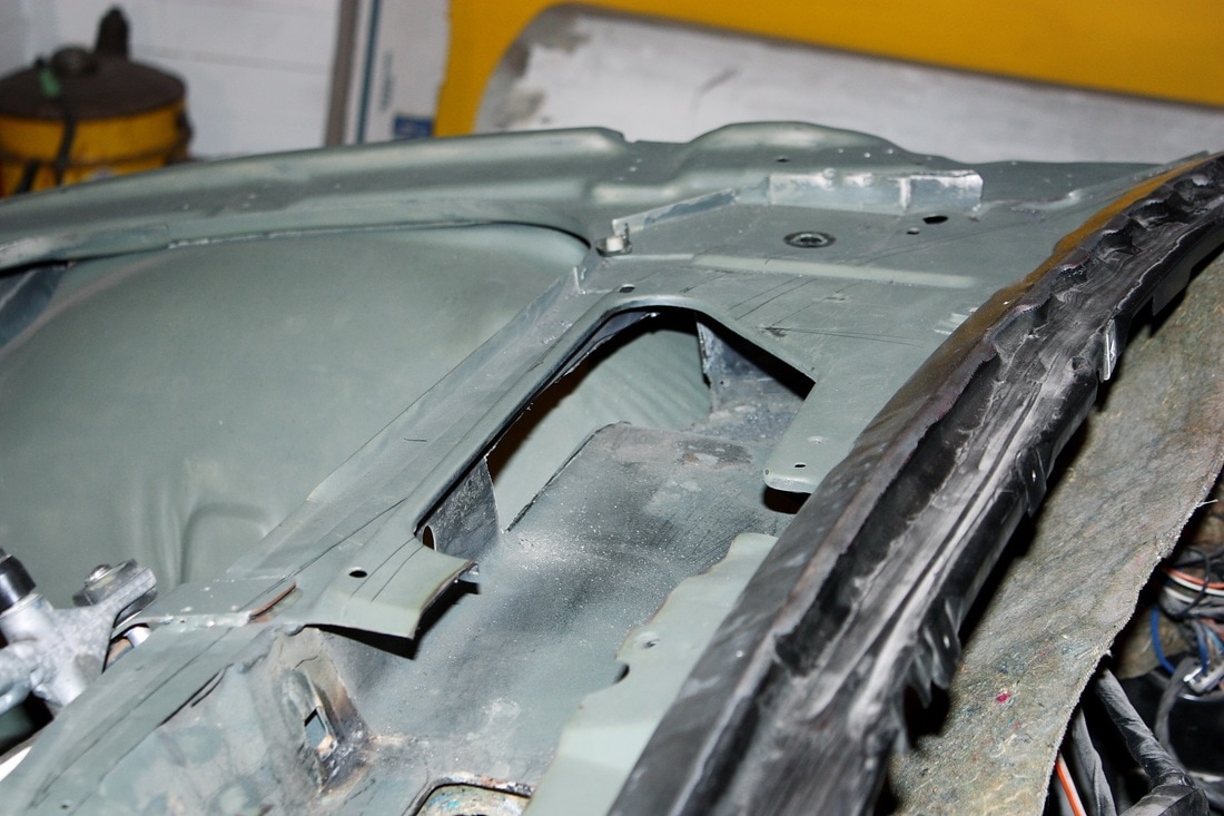
Next, I needed to gain access to the centrally located HVAC inlet. It's on the bottom of the cowl chamber and was hidden by the upper chamber sheet metal. I had to remove the hash-marked area shown in this next photo. This entire area will be strengthened again by the installation of my new lower metal windshield frame / dash extension:
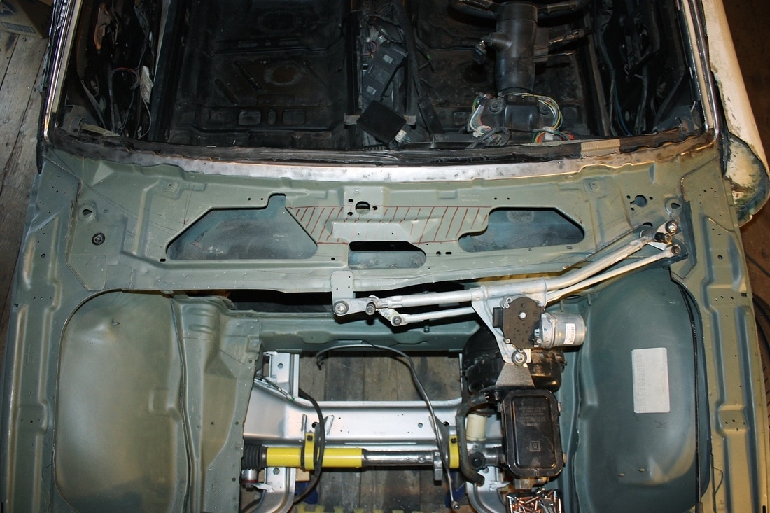
With the centre piece removed, the rectangular hole that leads directly into the HVAC unit became visible:
Here's a view from the driver's seat looking into the passenger side cowl chamber. The new cowl inlet is visible in the centre of the photo:
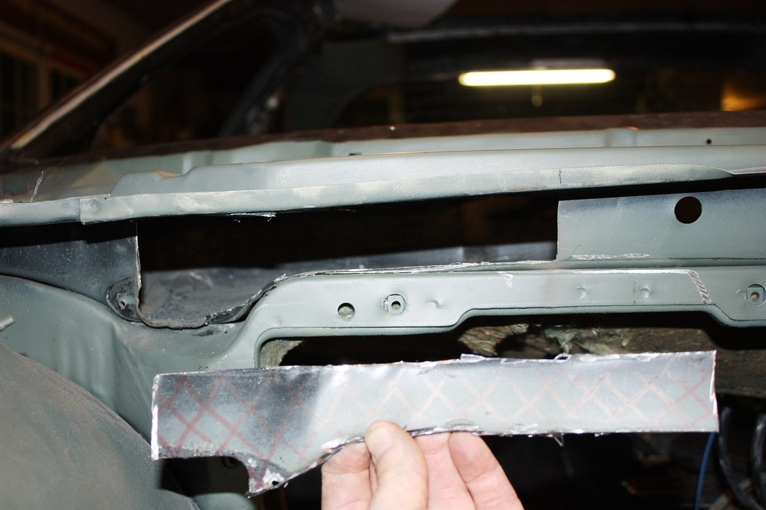
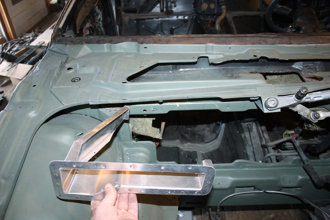
With that done, I started working on the sheet metal ducting needed for the new inlet and to separate the upper and lower halves of the cowl chamber. I began by making a template for the cowl inlet, then transferring it to some 6061-T6 aluminium, cutting it out, and bending it to shape:
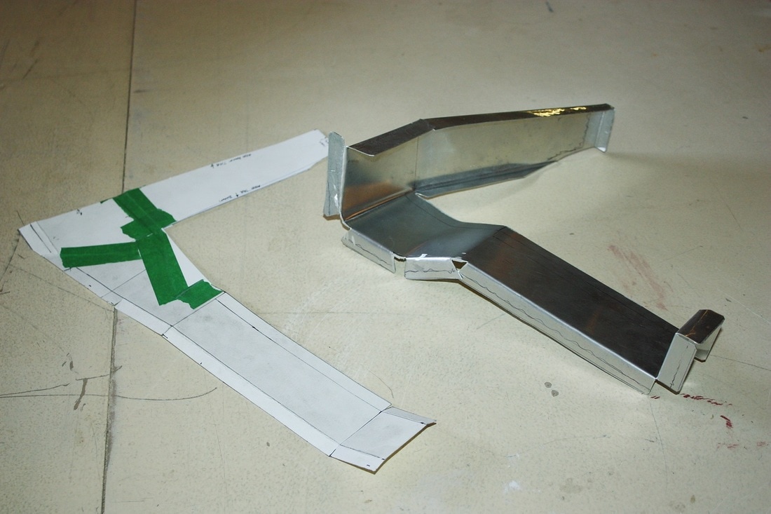
Then, since I'll eventually need some sort of 90 degree elbow or filter box to transition from the vertical cowl hole to the horizontal grill in the Sky/Solstice trim panel, I added a mating flange to the new inlet:
I mocked it up on the cowl to take the remaining measurements for the duct work between the new inlet and the centrally located HVAC inlet:
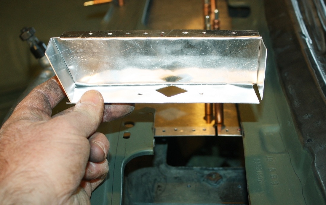
After trimming and fitting a half dozen prototype templates, I finally had a working plan for the rest of the duct. This next photo shows most of the system (albeit upside down). Missing is the end cap at the far left, and a seam doubler (both are shown later):
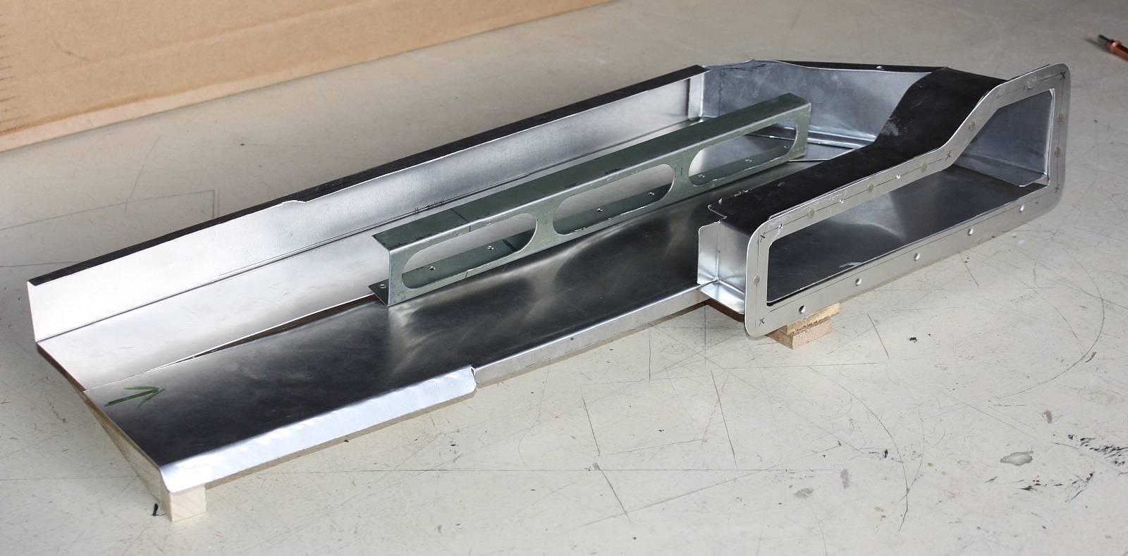
The curious looking centre brace was needed for two reasons. The first was that I couldn't fit the entire width of the new duct work into place without slicing it in half length-wise. So the brace provides a means to reattach both halves together. I could have done that with a simple strip, so the second reason for the centre brace was to stiffen to the broad ceiling against vibrations that might find their way into the cabin. I cut oval holes in the webbing of the brace to allow air to flow freely between both sides of it.
The cross sectional area of this part of the duct is 100 sq-cm (or 32 sq-cm less than the fan inlet), so it's reasonable to expect this will be the area with the lowest pressure in the intake system.
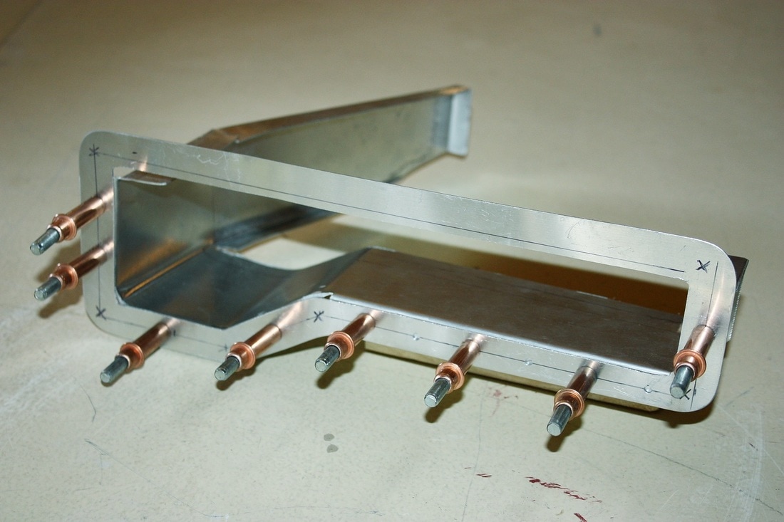
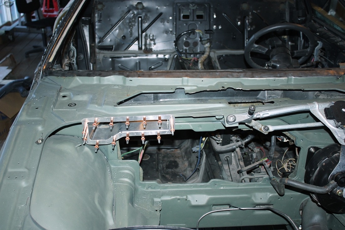
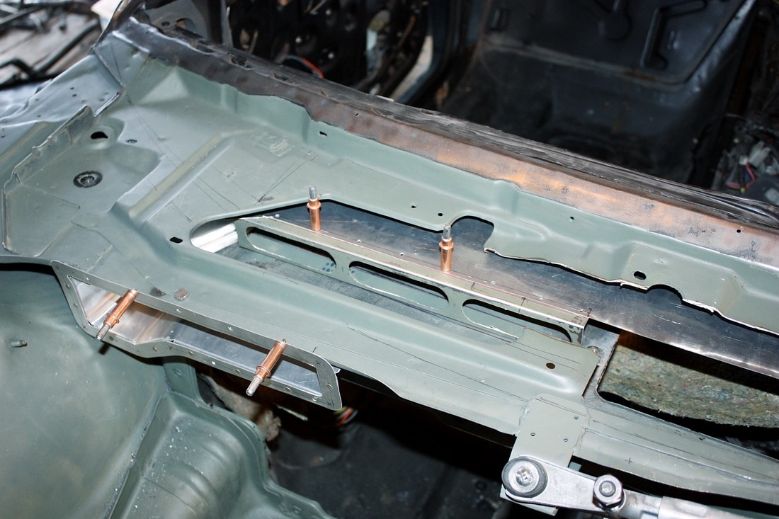
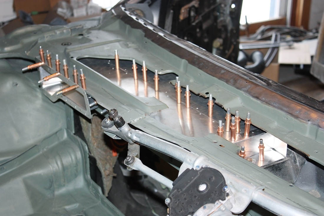
With all the pieces fabricated, I next mocked them up to drill the rivet holes that would attach the duct work to the chassis. First up was the cowl inlet...
... followed by the aft half of the "ceiling" and the stiffening brace:
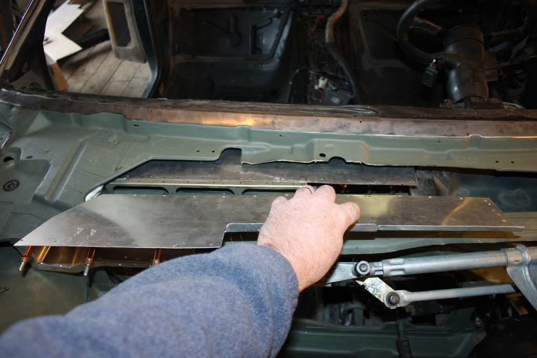
Next came the forward half of the duct ceiling. Here it's more obvious why I had to slice the ceiling in half. The two pieces together are wider than the slot in the top of the cowl:
And finally the end cap:
Here's the whole enchilada being held together with Cleco fasteners. The Cleco's keep the rivet holes aligned while drilling additional holes.
Once drilled, it all came out one last time for deburring, etching, priming, and painting. To reinstall it, I'll use a sealant between each piece before riveting it together for the last time.
Next up: the defroster circuit mods.

 RSS Feed
