Having ironed out the bulk of the front compartment structure, I tore it all apart to clean the fingerprints off the bare sheet metal, hit it with some Duplicolor self-etching primer, then applied a coat of 2K epoxy primer to everything:
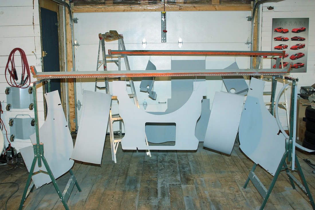
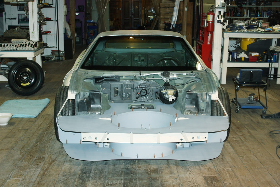
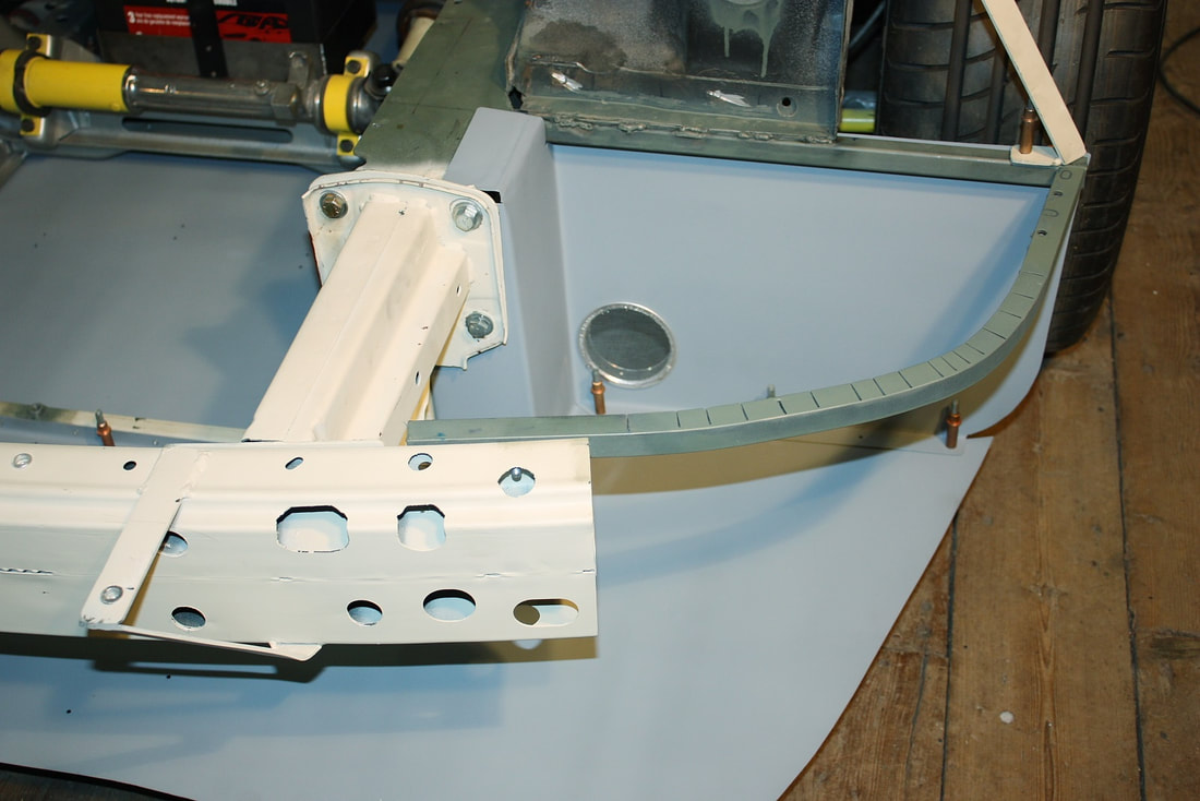
Once the epoxy had cured, I pinned it all back together again using Cleco fasteners to plan out which pieces should be permanently fastened to the chassis, and which ones I would make removable for access later on. When I stepped back I couldn’t help to think it looked like a cow-catcher on a train!:
Once the epoxy had cured, I pinned it all back together again using Cleco fasteners to plan out which pieces should be permanently fastened to the chassis, and which ones I would make removable for access later on. When I stepped back I couldn’t help to think it looked like a cow-catcher on a train!:
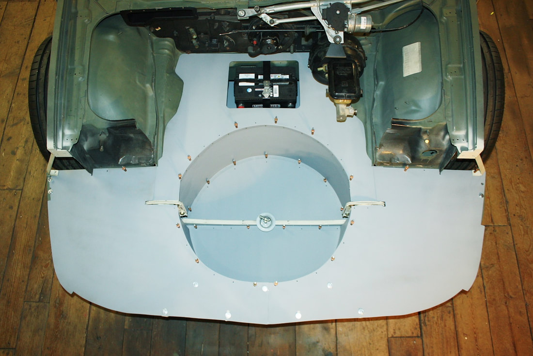
And from the top view it sorta looked like a hammerhead shark!
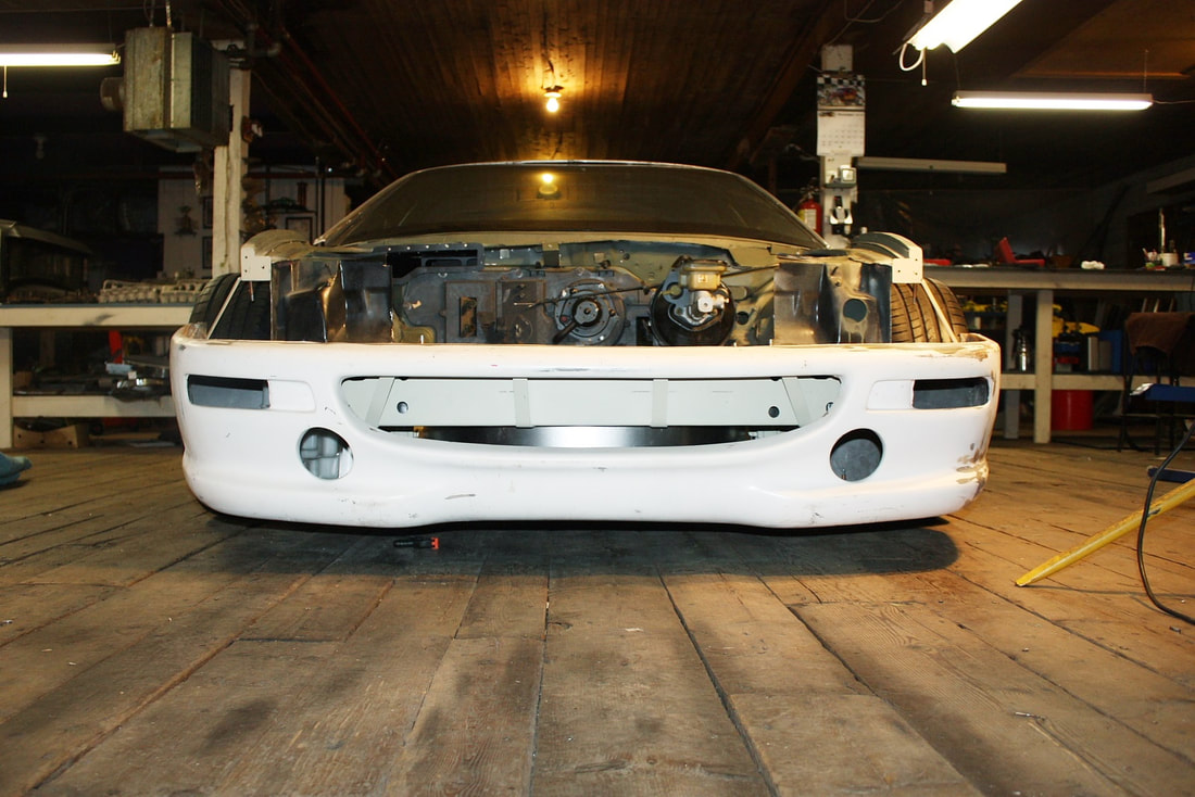
When I slipped the lower fascia back on, I realized I’d have to address a problem that's been brewing ever since I started compartmentalizing the front end: Airflow into the front grill would have nowhere to go:
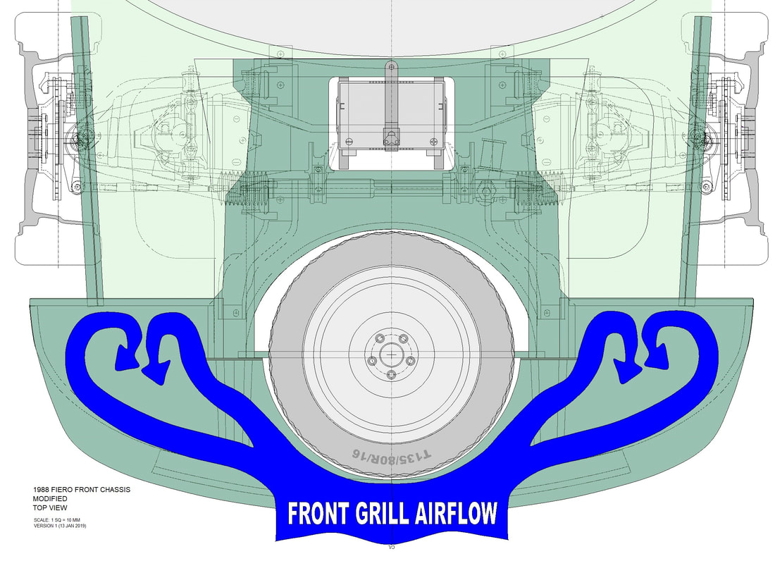
I thought about making rear facing louvers in the undertray, but then that would've just crammed high pressure air under the car and generated front end lift. Then I thought about ducting the air to the HVAC inlet, which I'll probably do, but not now. Finally, although my driving style won’t require it, I decided to duct the air to the front brakes:
I thought about making rear facing louvers in the undertray, but then that would've just crammed high pressure air under the car and generated front end lift. Then I thought about ducting the air to the HVAC inlet, which I'll probably do, but not now. Finally, although my driving style won’t require it, I decided to duct the air to the front brakes:
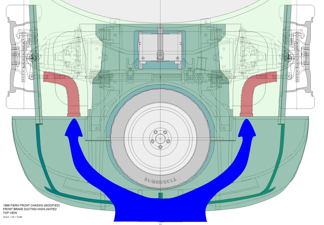
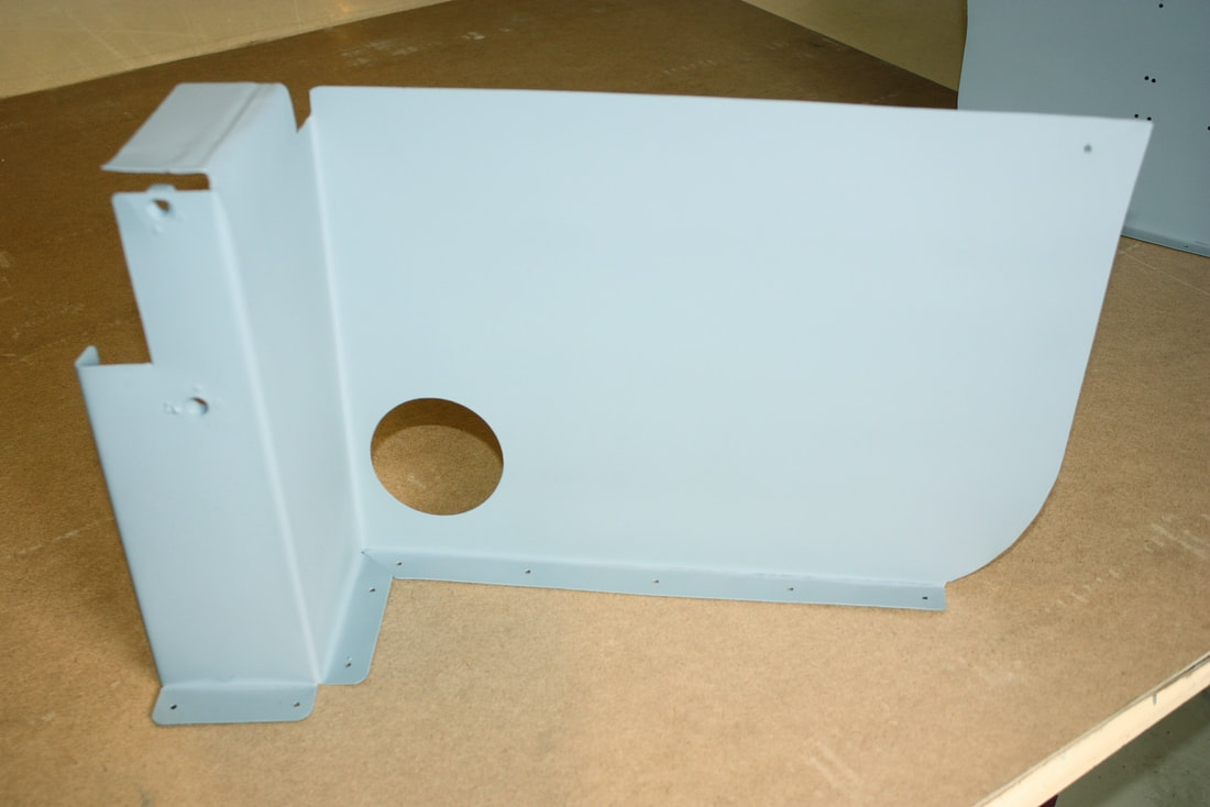
I started by cutting a 3” diameter hole into each of the bulkheads that separate the front compartment from the wheel well:
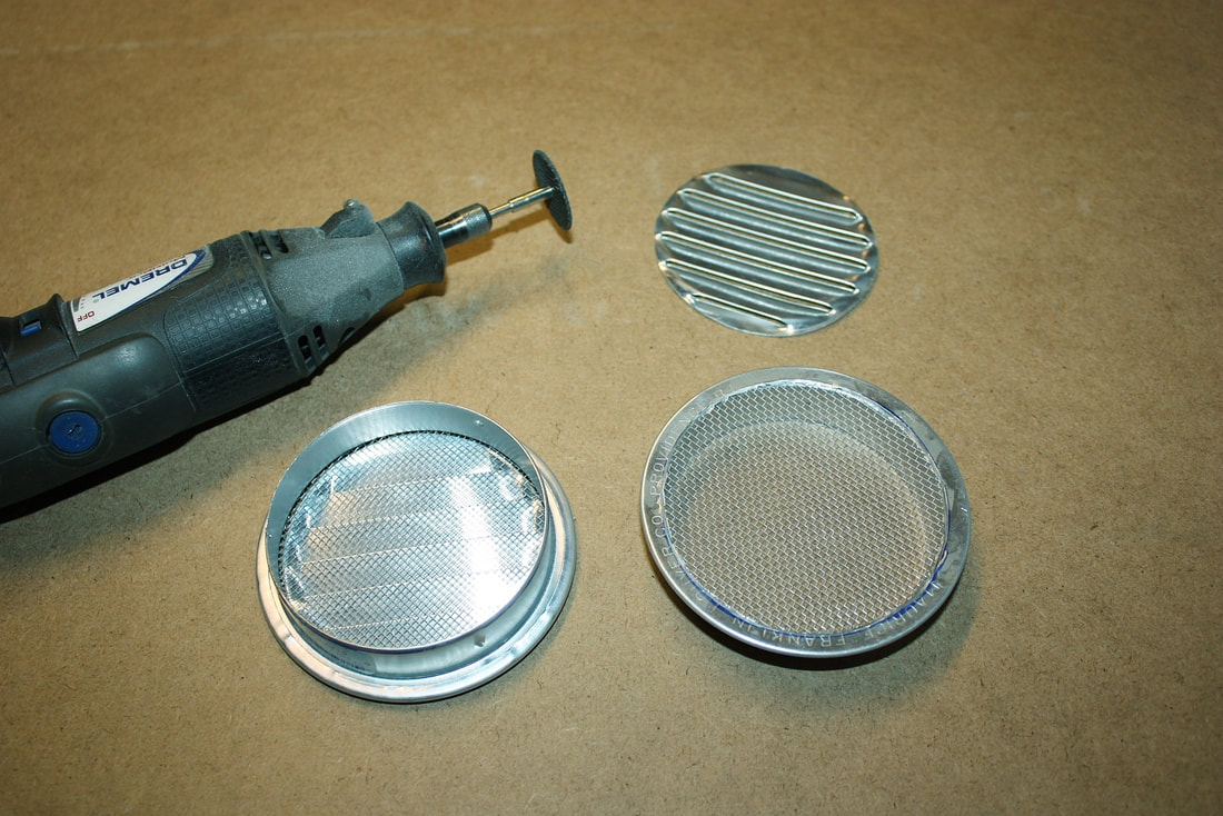
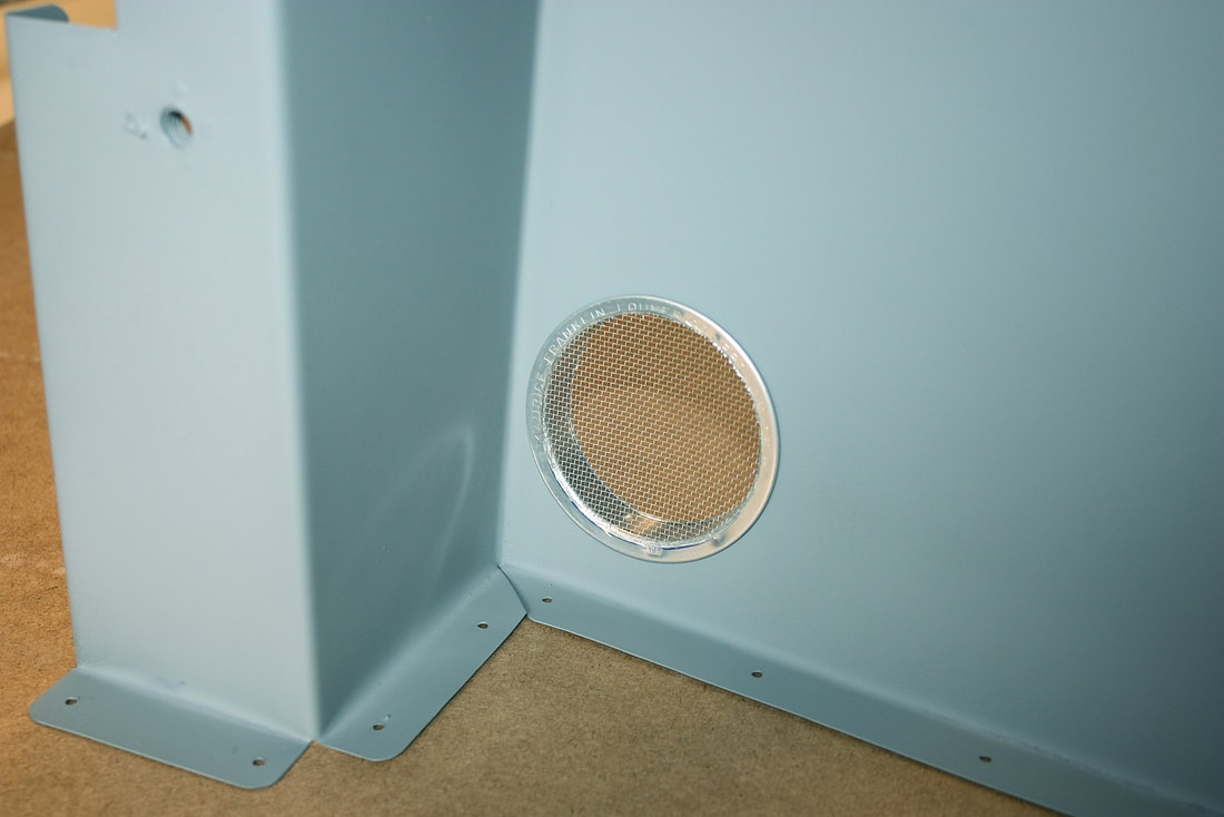
Then I bought a pair of 3” diameter vents from the local hardware store and proceeded to open them up, effectively turning them into mounting flanges for the ducting. I cut out the louvers but left the screening in place for now:
Then I bought a pair of 3” diameter vents from the local hardware store and proceeded to open them up, effectively turning them into mounting flanges for the ducting. I cut out the louvers but left the screening in place for now:
They slipped nicely into place, and were pretty solid after riveting them to the bulkheads:
Then I reinstalled the bulkheads:
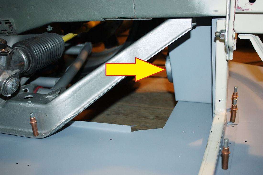
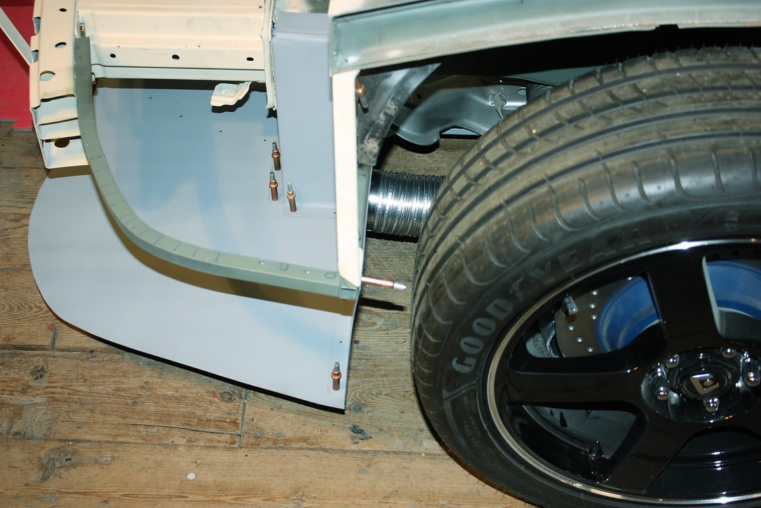
From this view you can see the brake duct flange (yellow arrow) sticking out into the wheel well, with the lower control arm and wheel in the background:
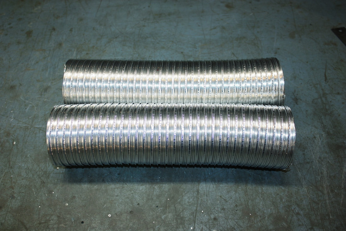
I bought some 3” diameter aluminium flex hose for use with a clothes drier for the actual ducting. At $12 it won’t be much of a loss if it turns out to be too flimsy for the job. In the meantime, I’ll keep my eyes open for something a little more robust:
I bought some 3” diameter aluminium flex hose for use with a clothes drier for the actual ducting. At $12 it won’t be much of a loss if it turns out to be too flimsy for the job. In the meantime, I’ll keep my eyes open for something a little more robust:
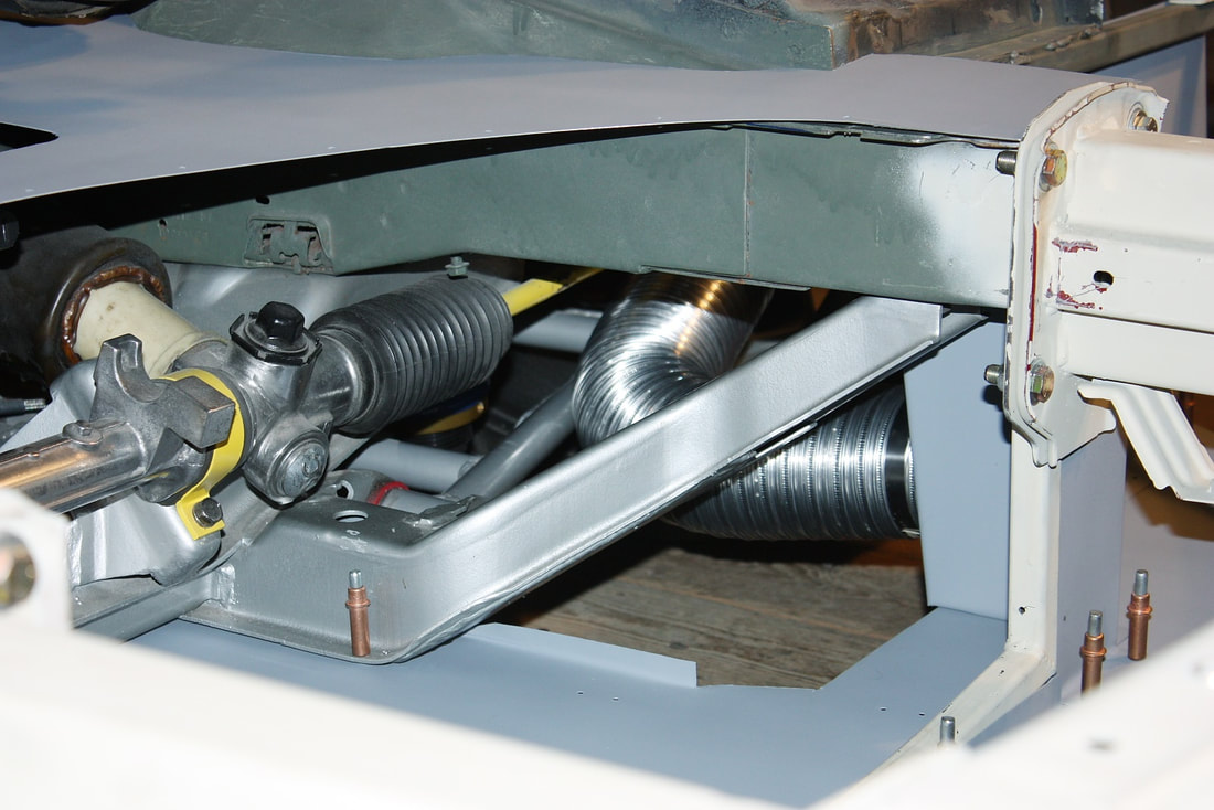
After forming 90 degree elbows in the ducting, I slipped them into place with ease:
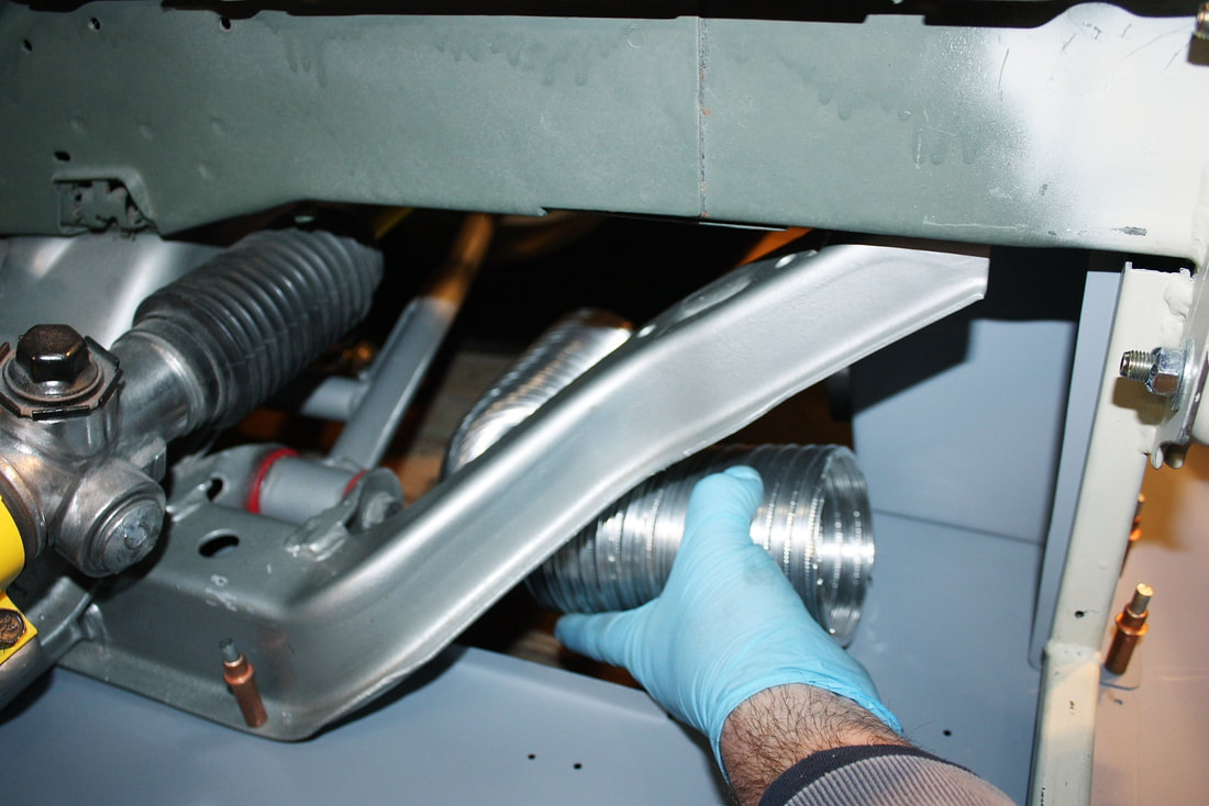
Then I clamped them to the freshly installed mounting flanges with a hose clamp. They’ll have to be clamped to the lower control arm as well in order to move up and down with the wheel, and they’ll have to be positioned to clear the steering arc of the tire as well, but I’ll work those details out later:
Then I clamped them to the freshly installed mounting flanges with a hose clamp. They’ll have to be clamped to the lower control arm as well in order to move up and down with the wheel, and they’ll have to be positioned to clear the steering arc of the tire as well, but I’ll work those details out later:
Whether two 3” ducts are going to be enough to vent the ram air coming through the front grill is yet to be seen, but if not, I can always put extra louvers in the bulkheads to vent excess pressure into the wheel wells.
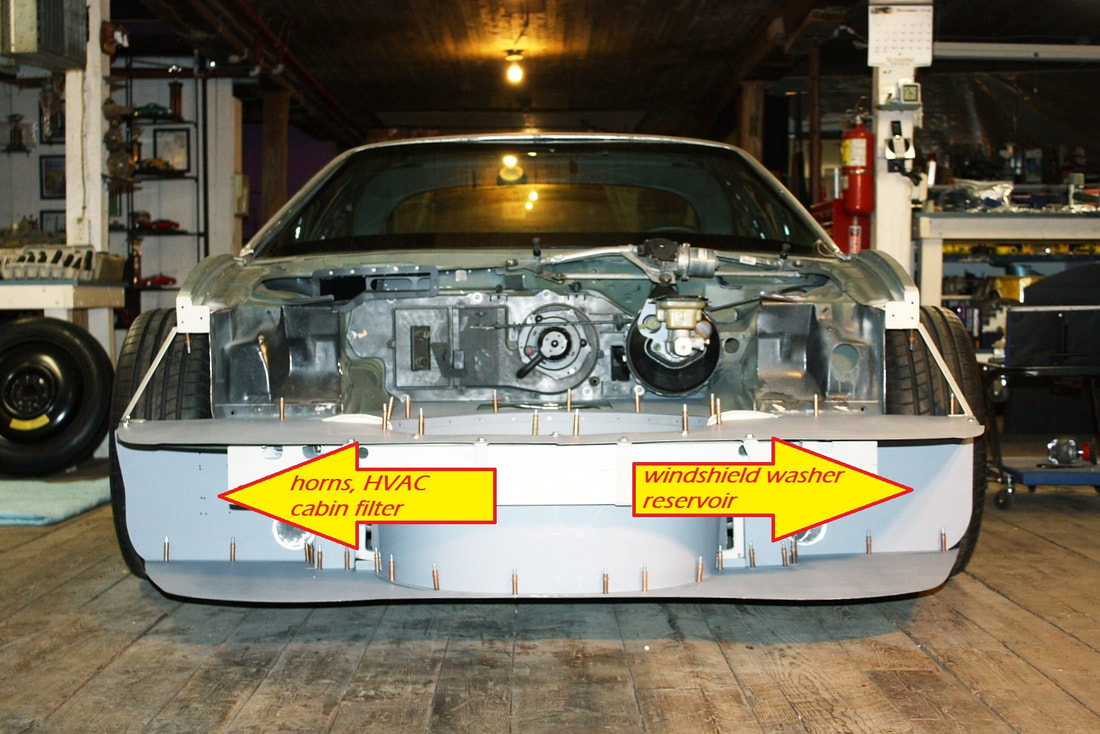
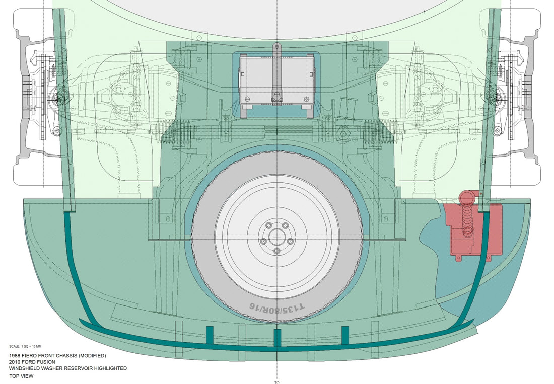
Since I was working in the general area, I decided I should at least plan the layout for a few other miscellaneous front end components. I'll use the passenger side front bulkhead to mount the horns and possibly a filter box for the HVAC system. Note how the HVAC inlet at the base windshield on the passenger side lines up well with this area. The driver’s side will get the windshield washer reservoir:
Whether two 3” ducts are going to be enough to vent the ram air coming through the front grill is yet to be seen, but if not, I can always put extra louvers in the bulkheads to vent excess pressure into the wheel wells.
Since I was working in the general area, I decided I should at least plan the layout for a few other miscellaneous front end components. I'll use the passenger side front bulkhead to mount the horns and possibly a filter box for the HVAC system. Note how the HVAC inlet at the base windshield on the passenger side lines up well with this area. The driver’s side will get the windshield washer reservoir:
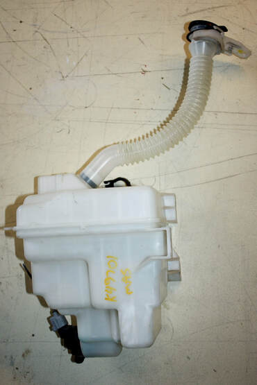
Knowing what physical space was available for the windshield washer reservoir, I set off for the salvage yard again, this time hunting for a part that’s often hidden behind body panels. Luckily I didn't have to look too long before stumbling across a 2010 Ford Fusion with the RH front fender and facsia removed. It looked to be the perfect shape and size!
Knowing what physical space was available for the windshield washer reservoir, I set off for the salvage yard again, this time hunting for a part that’s often hidden behind body panels. Luckily I didn't have to look too long before stumbling across a 2010 Ford Fusion with the RH front fender and facsia removed. It looked to be the perfect shape and size!
And because of my crazy desire to document everything, I drew it out in two dimensions…
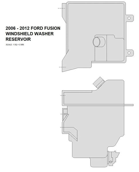
… and added it to my chassis drawings:
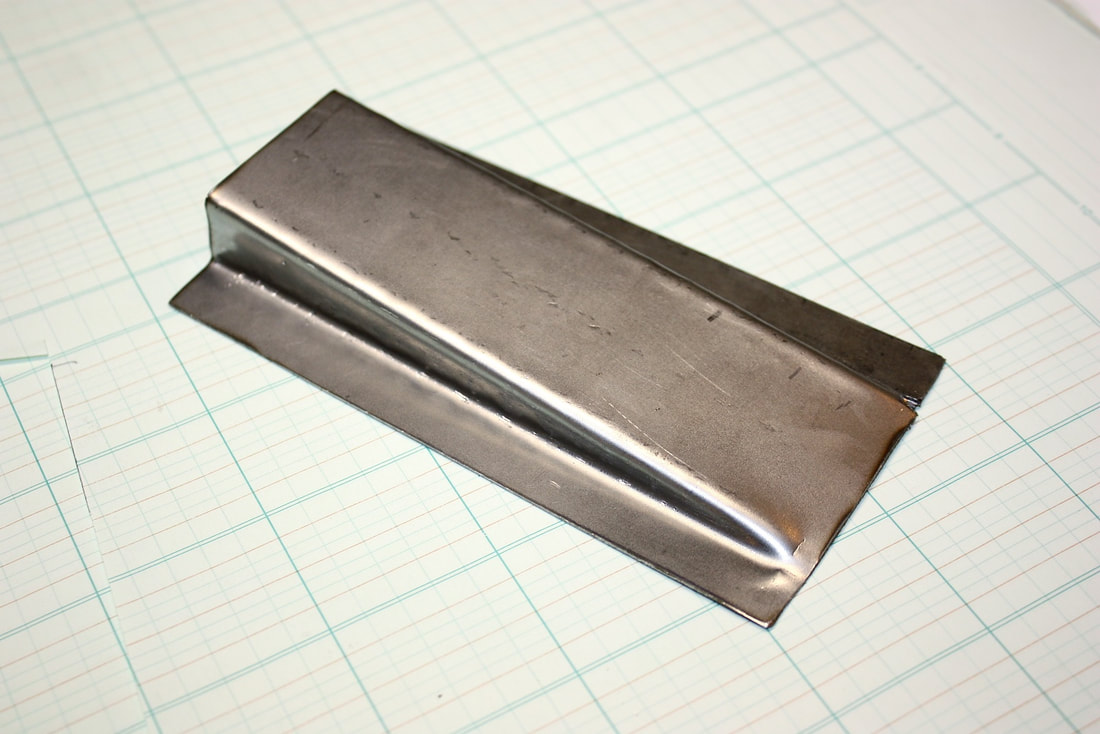
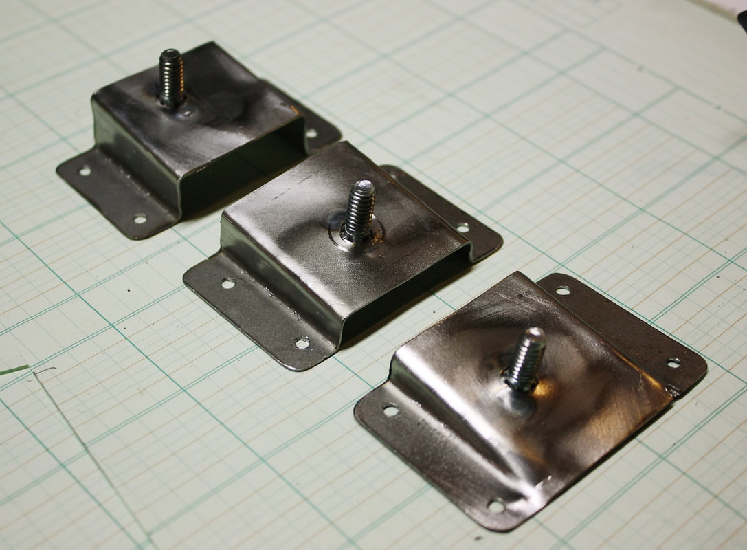
The front compartment bulkhead that I wanted to mount the reservoir to, wasn’t made perfectly vertical… I made it with a 10 degree slant, which meant that I’d have to make oppositely angled mounts for the reservoir to sit level. Since I needed three mounts for the reservoir, and since they were all at different heights, I was able to form a single 10 degree bracket that I could simply cut in three pieces:
The front compartment bulkhead that I wanted to mount the reservoir to, wasn’t made perfectly vertical… I made it with a 10 degree slant, which meant that I’d have to make oppositely angled mounts for the reservoir to sit level. Since I needed three mounts for the reservoir, and since they were all at different heights, I was able to form a single 10 degree bracket that I could simply cut in three pieces:
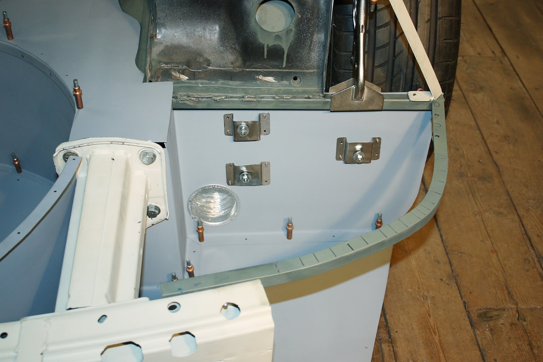
After marking the appropriate spots on the bulkead, I drilled mounting holes and mocked up the mounts:
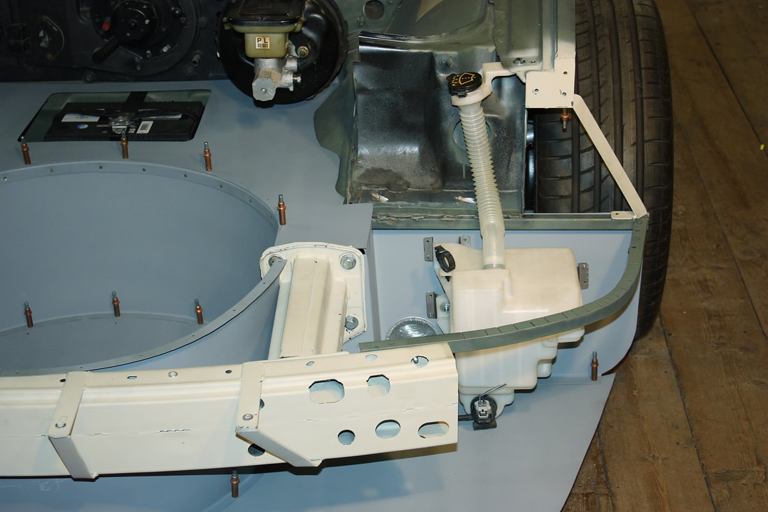
Then I bolted the reservoir to the bulkhead… easy peasy. Even the filler neck turned out to be at the right height to bolt to the upper frame rail. I’ll shorten the mounting tab on the neck to straighten it out.
Then I bolted the reservoir to the bulkhead… easy peasy. Even the filler neck turned out to be at the right height to bolt to the upper frame rail. I’ll shorten the mounting tab on the neck to straighten it out.
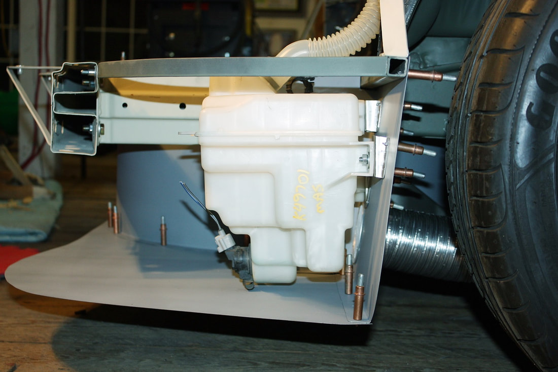
Finally, this next photo shows why I needed the funky mounting brackets I made to get the tank sitting level, and to direct the last little bit of fluid to the side with the pump:
I'll use a similar approach to install the horns and HVAC cabin filter on the passenger side, so I'll spare you the details. Besides, I've got to keep the last two posts I've reserved in this section to cover the entire fuel system at some later point.
For now though, it’s time to head over to the Body section!

 RSS Feed
