The next step was to do the same to new frame rails as I did to the original ones: I separated the rail halves by centre-punching each spot weld, drilling a 1/8" pilot hole, then drilling out each weld with a 21/64" drill bit (one size larger than 5/16").
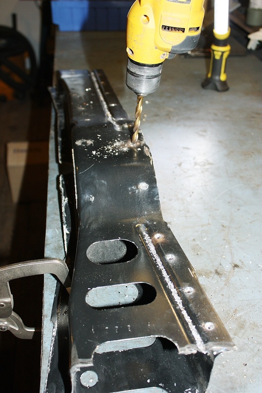
Once each spot weld was drilled out, I needed to wedge a small cold chisel between the weld flanges to finish the job. Each spot weld literally "popped" apart as I made my way along the weld flange. It was much easier than I expected.
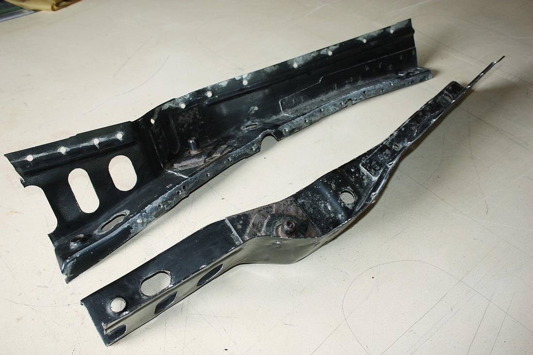
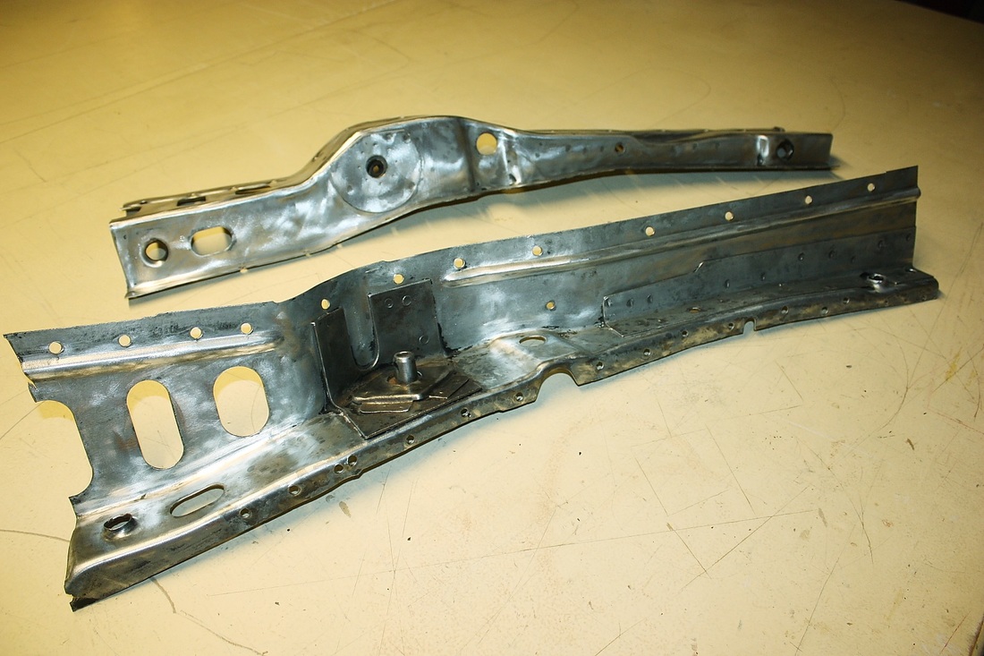
Not wanting to give up the opportunity to really protect this area, I decided to strip the OEM paint off the new rails since there were many small pencil eraser sized spots where the paint was flaking off here and there. I used a gnarly wire wheel on my angle grinder so it went pretty fast... 45 mins per rail half.
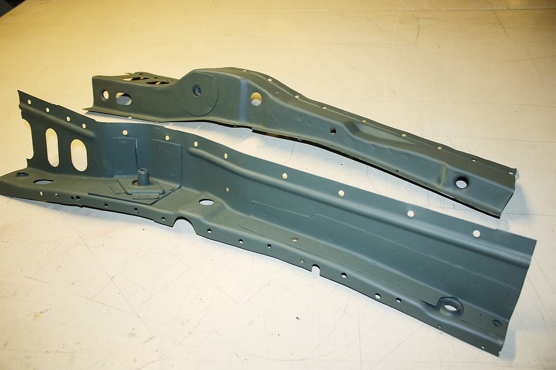
Then I primed them inside and out:
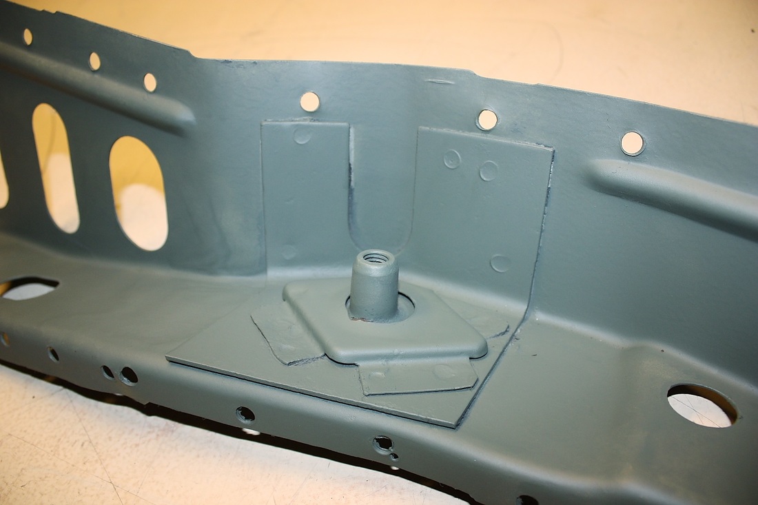
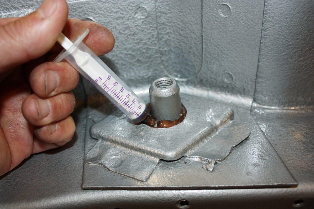
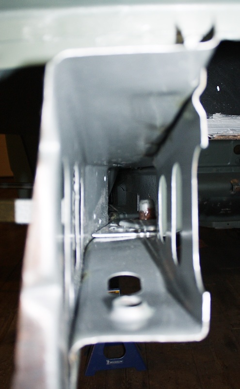
Here's a close up of what the captured nut inside the frame rail is supposed to look like. The nut is what the the rear engine cradle bolts to. Notice the frame stiffener too.
I did the same to the rail halves that stayed attached to the car too... priming them with a self etching primer.
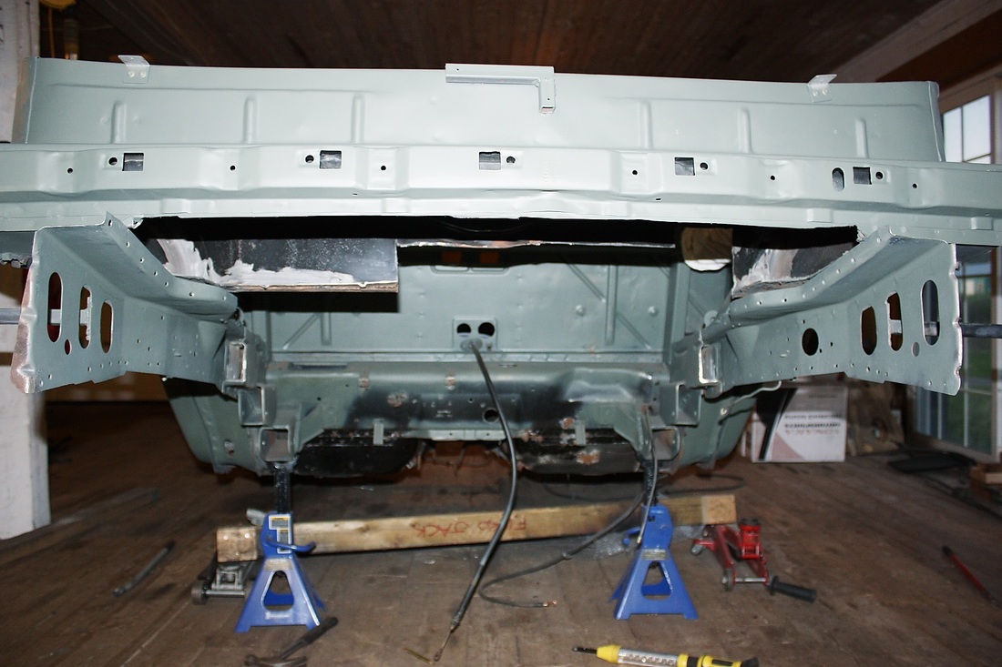
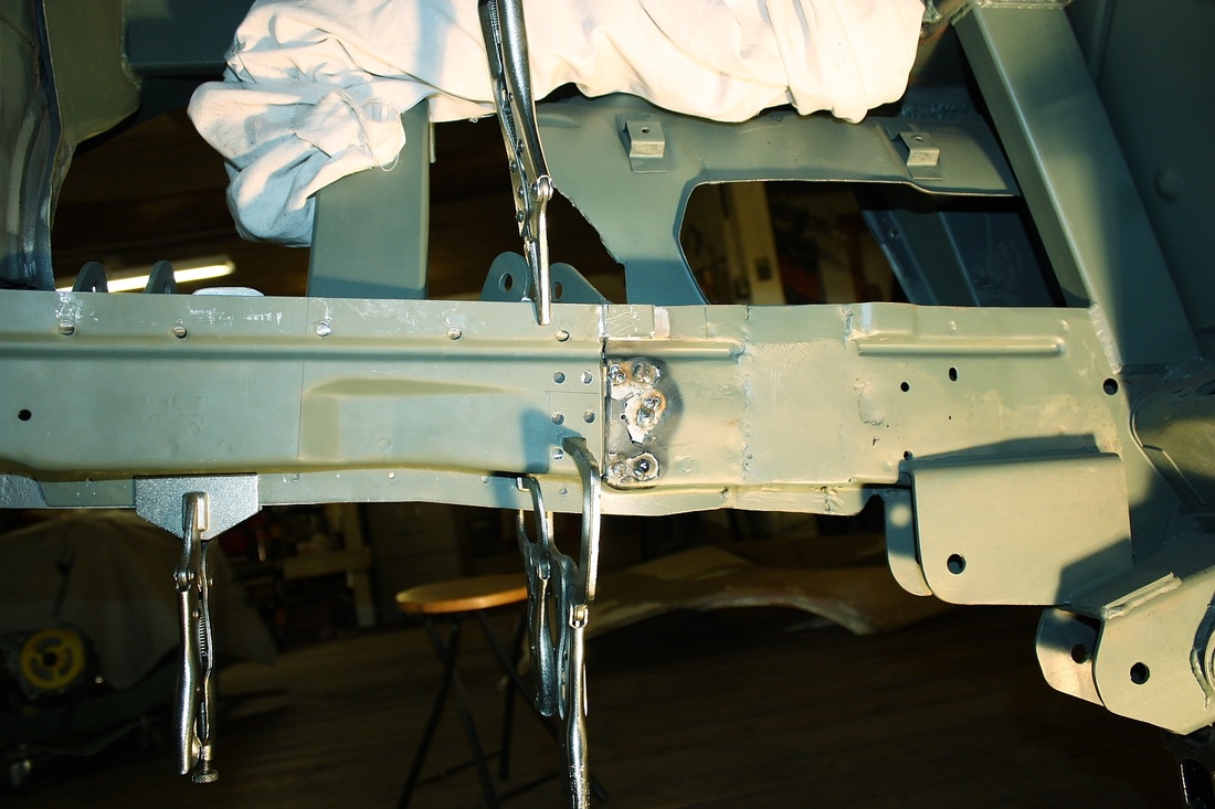
I then trimmed and fitted the new rail halves to fit the chassis. Luckily it wasn't as difficult as I expected. There is some misalignment tolerated in the side-to-side and fore-and-aft directions since the captured nut allows about 5 mm's of play in all directions except vertically. The vertical alignment was a piece of cake though because of a stamped bead running most of the length of the inboard wall of the rail, about an inch below the top. That bead butts up against the "ceiling" of the rail half still attached to the chassis. Here's the driver's side mocked up:
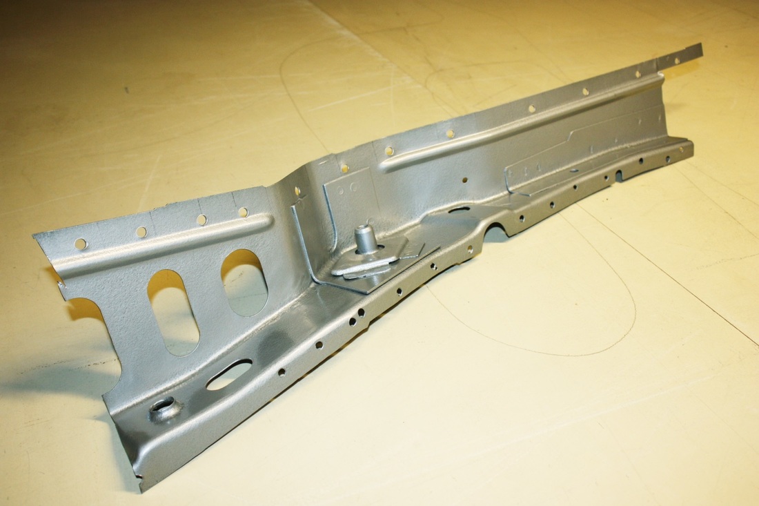
Once the alignment was checked and double-checked, I took the rail half off again and painted the inside silver with a hammered finish making it look like galvanized steel:
Having seen the ravages of rust on the original cradle nut, I decided to take extra steps to protect the new one from rusting and seizing. I sucked up some anti-seize compound into a syringe and squirted it into the cage from the top and bottom until it was good and goopy.
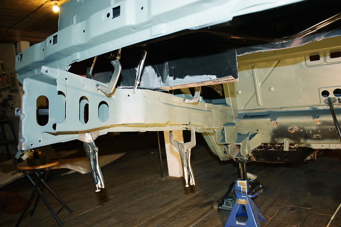
Then came time to splice the new inner frame rails onto the outer rails still attached to the chassis. I made a 3" long splice out of some rectangular tubing and buried it halfway into the rail on the chassis. I had drilled a series of 5/16" holes in the rail itself to rosette-weld the splice in place. I also needed a small thin doubler at the top to compensate for thickness of an OEM doubler that only ran partway up the inside wall. It looks nasty but that's just the paint flaking off due to the heat:
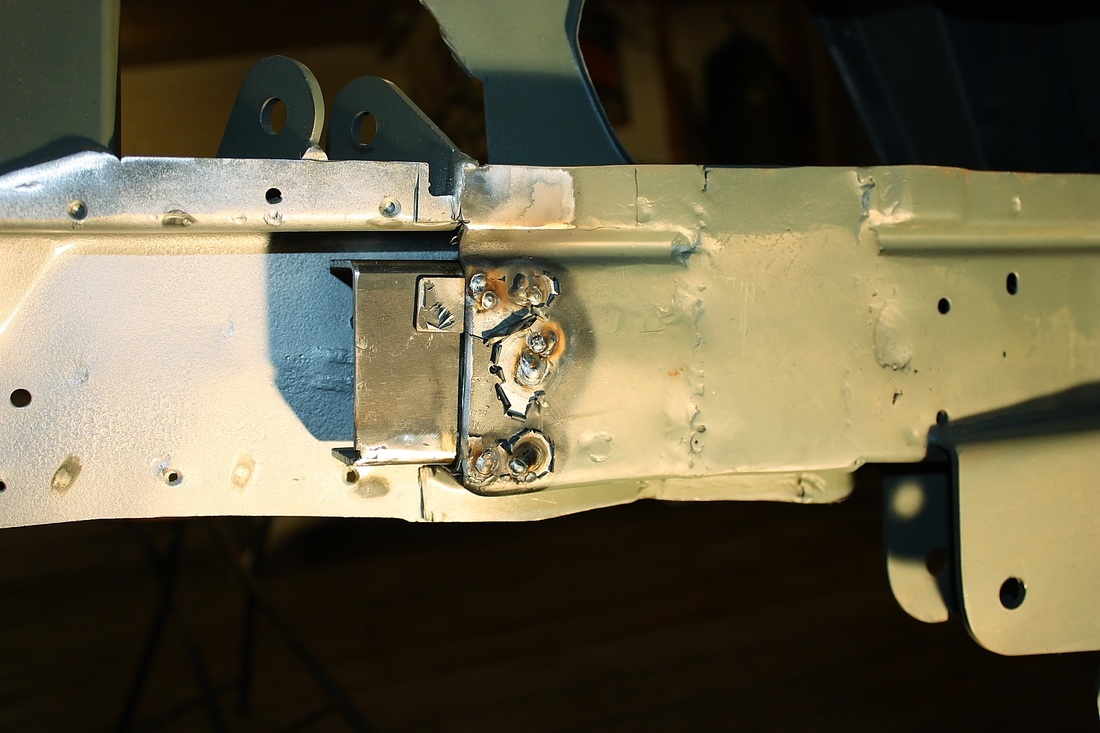
The splice is as much for strength as it is a backboard for welding up the vertical seam since it was difficult to get a really tight fitting butt joint with all the alignment steps. Here the new rail half has been clamped in place and is ready for final welding. Notice the six 5/16" holes in the rail at the seam for rosette-welding. There are two more on the bottom side.
Once the seam was welded up, it was just a matter of welding in the drilled out spot welds along the top and bottom flanges. The job was made easy because the drilled out spot-welds were in different locations between the old and new rail halves. That meant that behind every hole in the new rail half, there was solid metal behind it on the old rail half.
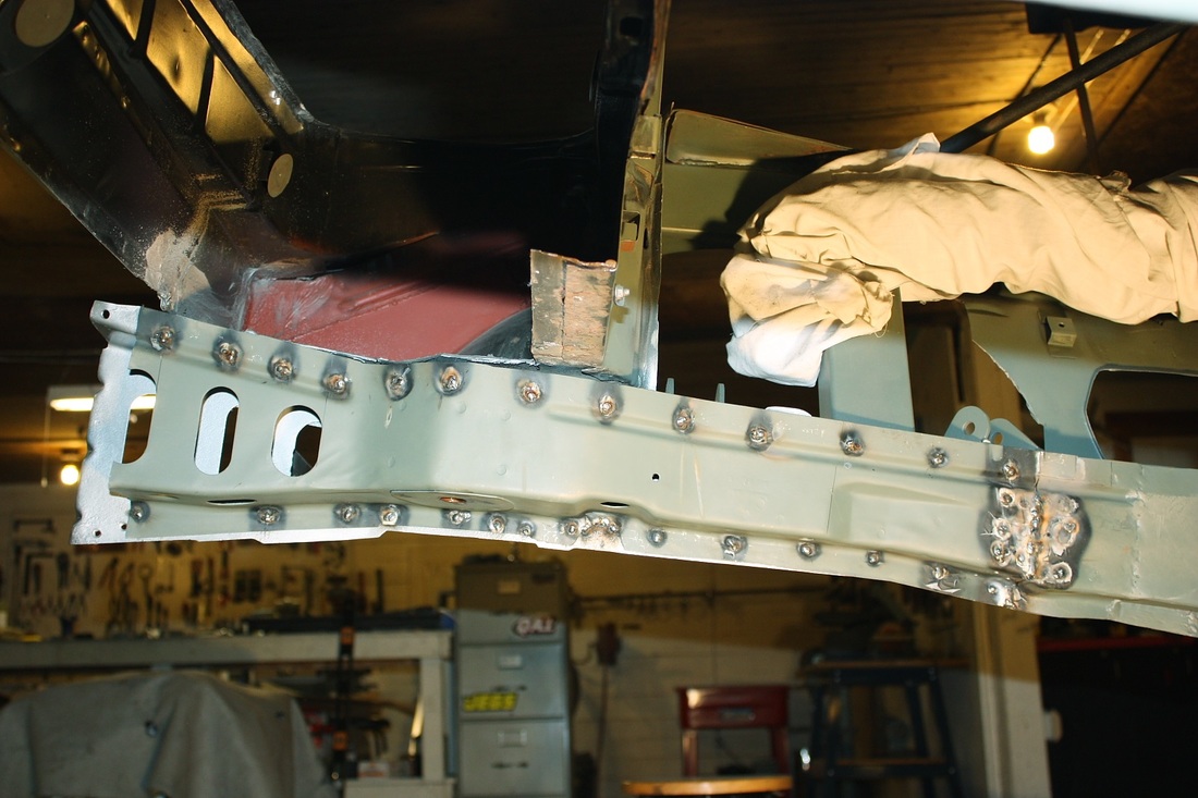
And finally, a peek down the inside of the LH lower frame rail... nice and clean... well except for the anti-seize compound oozing out everywhere!
Once the driver's side lower frame rail was restored, I tackled the passenger side in about half the time. Funny how that works.

 RSS Feed
