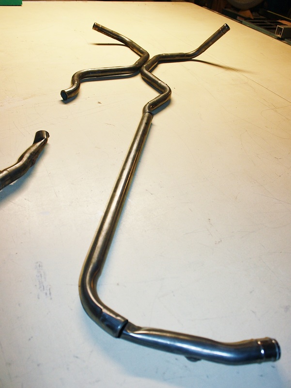
On with fabrication! I wanted the tubing and hoses for the coolant system to blend in as much as possible with what you'd expect to see in a production car. I certainly didn't want to use copper tubing or anything of that sort. I also felt it would be a sin if I couldn't figure out a way to salvage the miles of the stainless steel radiator plumbing that came stock on the Fiero. I forgot to take a photo of the Fiero tubes before I started hacking them up but this gives an idea how long they are:
They had suffered the kind of damage many Fieros experience: someone had accidentally crushed them by trying to raise the car by the rocker panels:
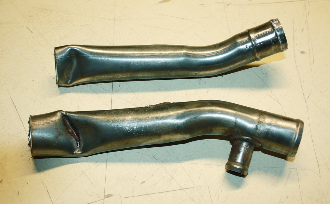
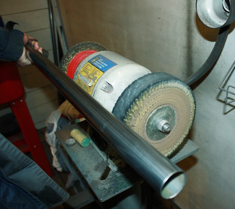
They were unsalvageable for that reason so I felt no remorse cutting them up for a good cause. Being made of stainless, I decided to sand the pieces down and give them a quick buffing on the polishing wheel:
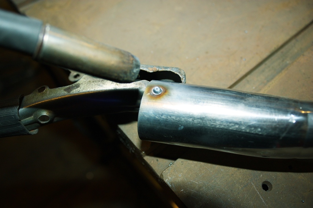
Then, tearing a page from a friend's LS4 Fiero build (thanks Paul!), I made sure the hoses and hose clamps wouldn't slip off the ends of the newly polished pipes by welding a couple raised dots around the circumference of each end.
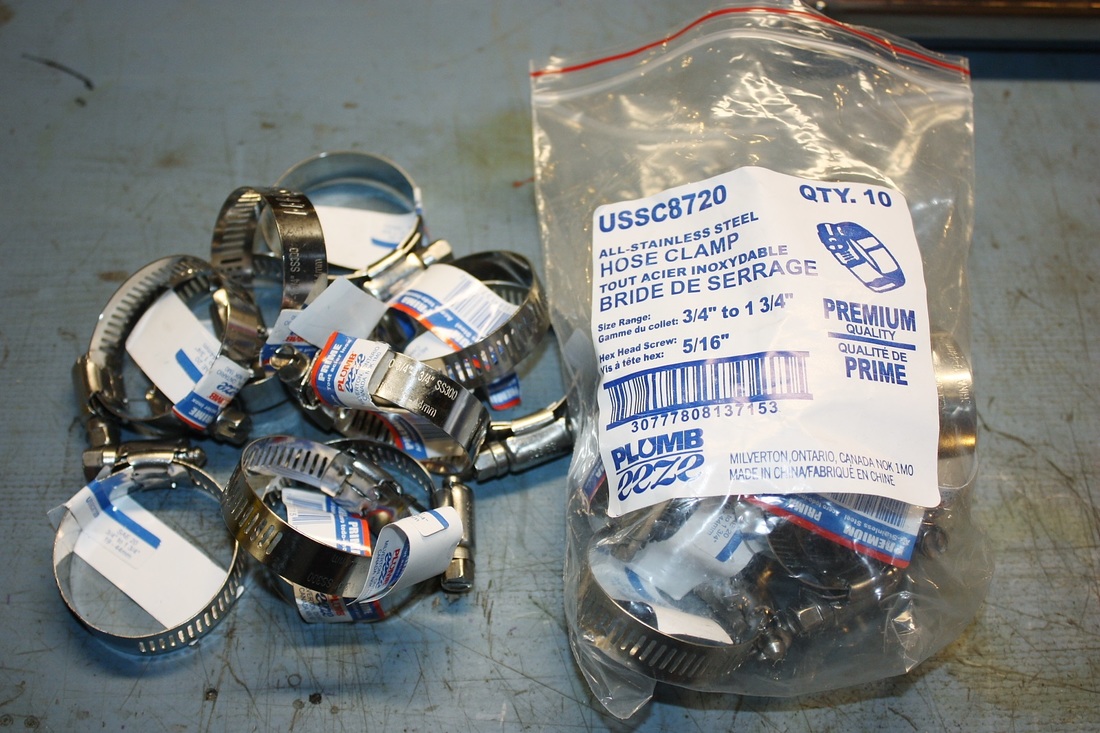
Next I went on the hunt for some all-stainless hose clamps. I tried NAPA only to find the typical stainless band with cadmium plated bolts. I finally found what I was looking for at a local hardware store for 70 cents cheaper per clamp than the NAPA clamps.
Here are all the stainless steel bits I needed to form the coolant system:
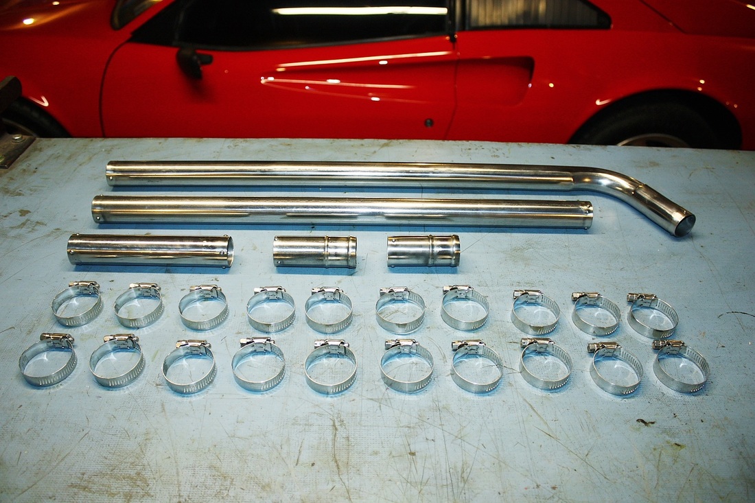
The long pipes are the straight sections used across the width of the firewall to reach the RH radiator, and the shorter ones are unions to join various rubber hoses together for the intricate shapes needed around the LH radiator.
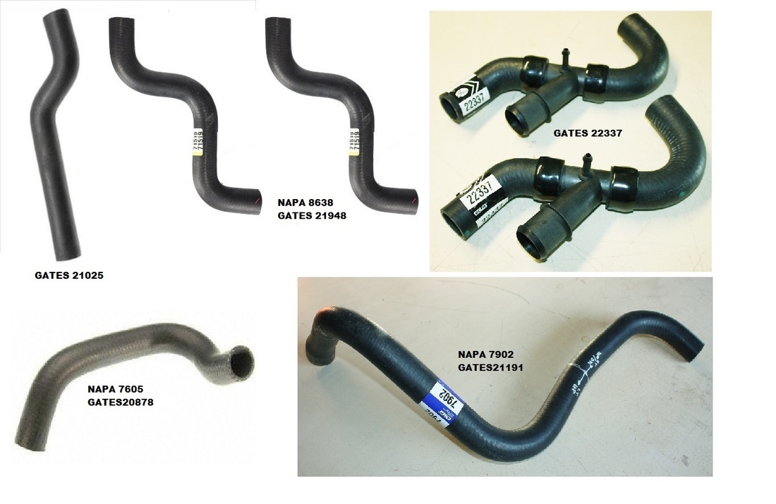
The next big challenge was finding pre-formed hoses that were shaped close to what I needed. I spent a lot of time scouring the Summit Racing and RockAuto websites for part numbers that appeared about right, then headed out to NAPA armed with a hockey-sock of numbers to see the hoses in person. I came up with this final list of parts for my car:
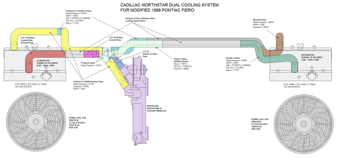
And here's a map of where each hose was used. Note that some hoses were cut down and others like NAPA 7902 were cut into three separate pieces, all of which were used in different areas!:
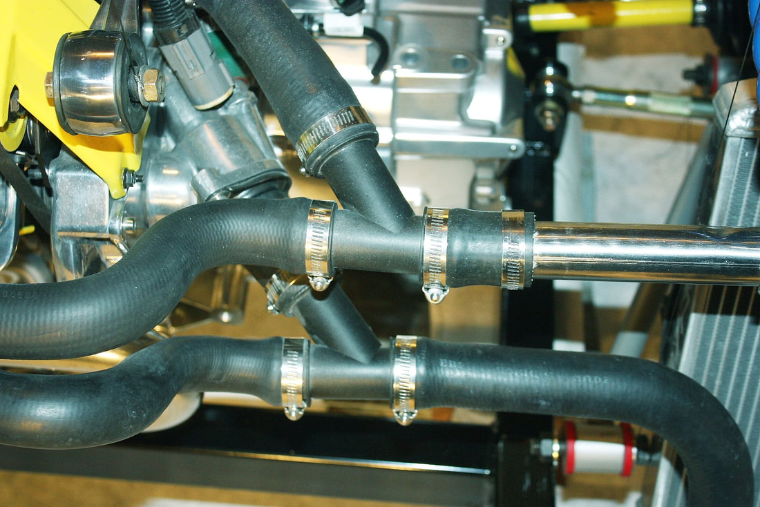
The most challenging of all was finding a suitable Y junction. I probably spent 12 hours alone looking for a suitable Tee or Y with two 1.25" outlets and one 1.5" outlet. There simply wasn't anything out there so I was ready to buy four 90 elbows to cut up and weld together to form two Tee's. Parts and shipping would've come to about Cdn$200! Luckily I happened to stumble across the '96-'00 Ford Taurus part shown above for a mere $20 each. They were a perfect match, although I didn't need the rubber hoses that came with them, so I carefully cut through the plastic hose clamps and took them off:
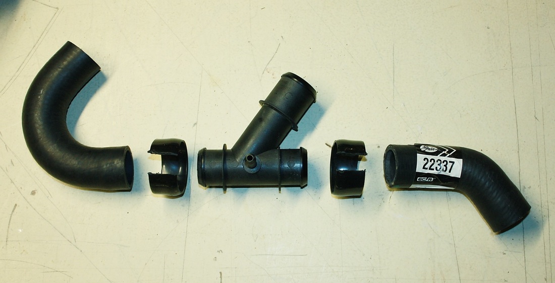
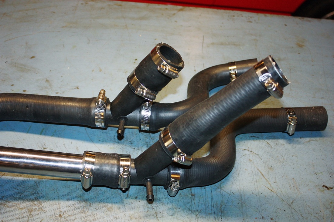
They matched the angles of the outlets on the Northstar pump housing perfectly. Here's a close up of how both Y's were integrated into the junctions near the pump:
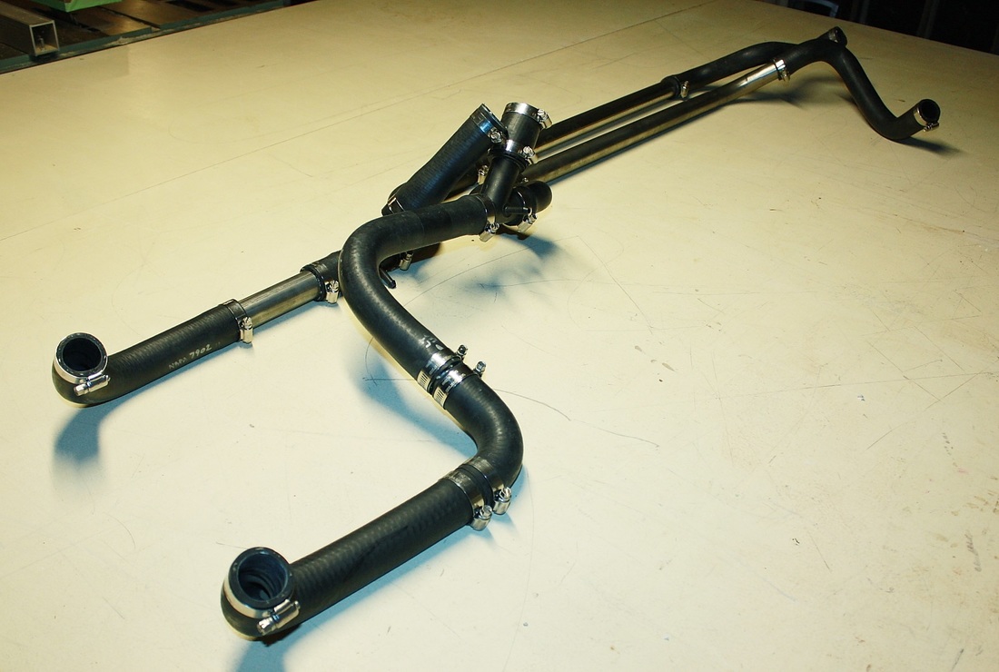
Stepping back a bit, here's the entire hot and cold circuit plumbing before being installed on the car. It was a lot easier to visualize the layout on the work bench than after it was installed.
Here's the system installed up against the firewall keeping it away from the heat as much as possible. I still need to consider where to install a fill point, but that will have to wait until I know more about how much room I have, and where.
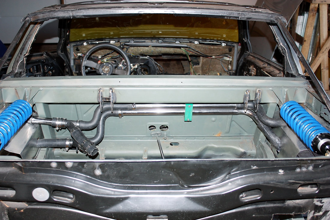
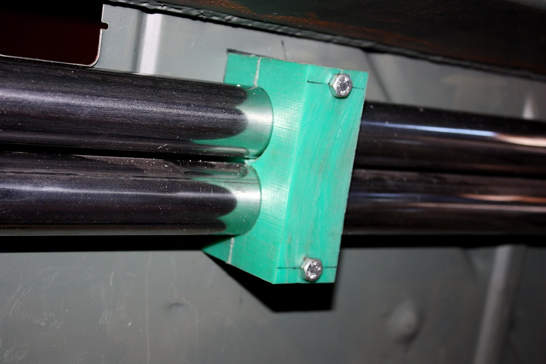
To mount the pipes to the firewall I made a plastic mounting block, drilled a couple holes for the tubes to pass through, and used some threaded inserts in the firewall to bolt it up tight:
Once the engine was back in, there was no way to see the entire system in one photo so here's a series of photos following the plumbing from the driver's side, to the pump:
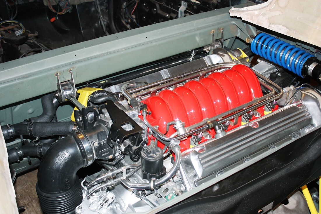
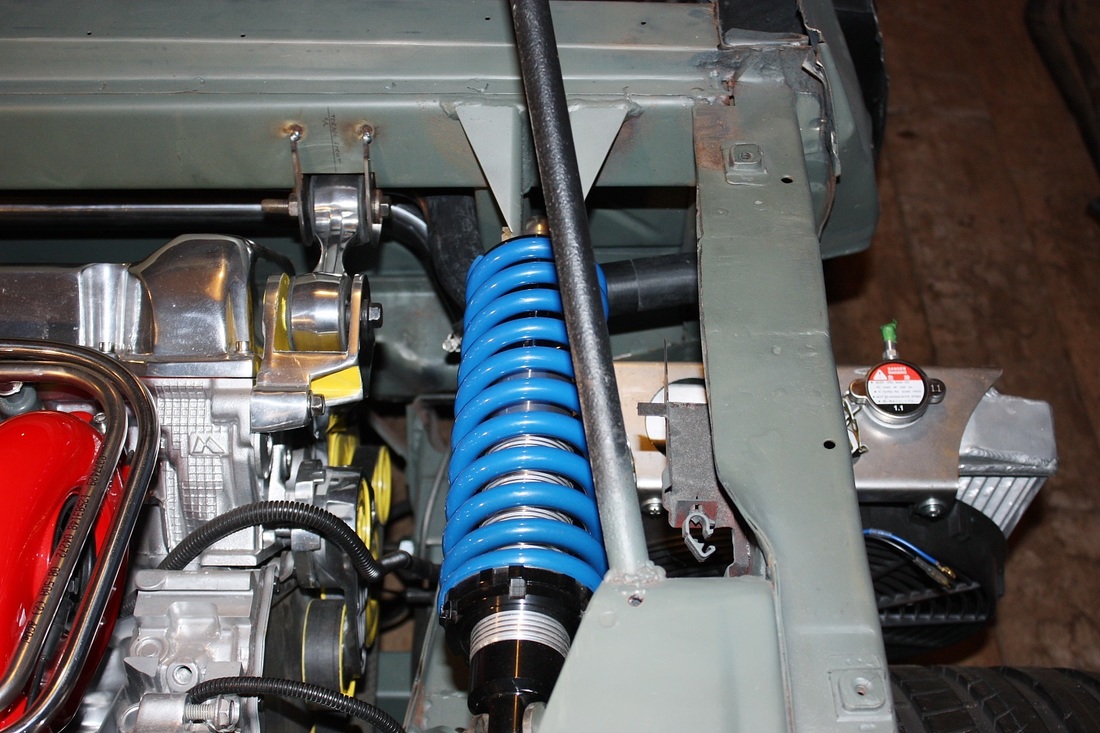
From the LH radiator both tubes cross over the lower frame rail and meet up with the Y junctions right behind the driver's seat. The upper circuit runs to the hot water outlet on the pump and the lower circuit to the cold water inlet:
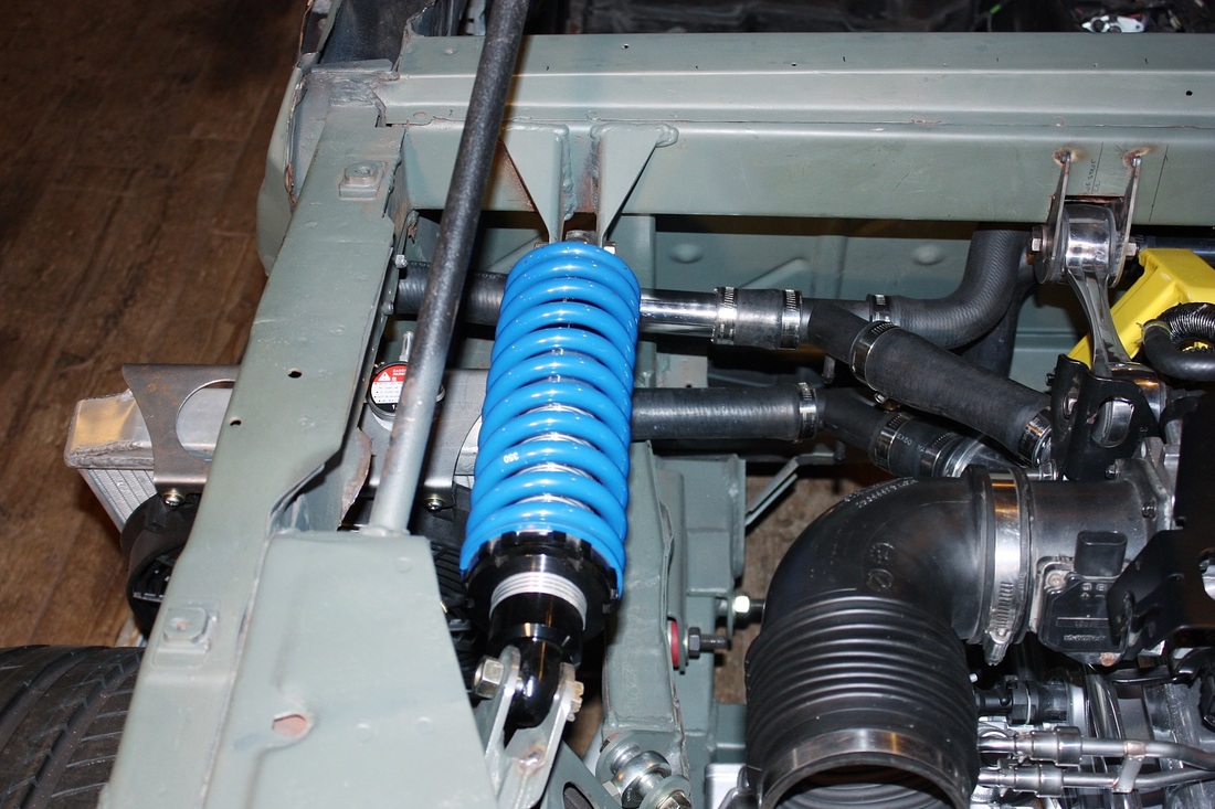
The branches heading to the passenger side zig-zag to the long stainless steel pipes along the firewall. Given that the exhaust will be close-by, it's not a bad idea that this section was made in steel. These were also the hardest sections to photograph:
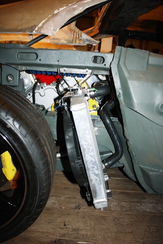
Once the stainless pipes reach the passenger side, the circuits had to zig-zag backwards again to clear the vertical support member I added to bridge the lower frame rail to the new upper cross beam:
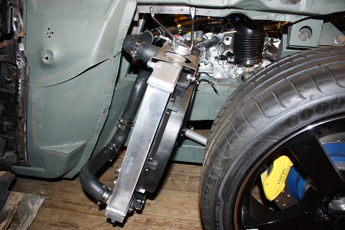
Finally the hoses exit just ahead of the passenger side radiator and plug in without much room to spare:
At this stage I still needed to add clamps to secure the plumbing to the chassis here and there, but I decided that would be most easily done the next time the cradle was pulled out. Work now had to focus on making modifications to the fibreglass shrouds in order to clear the new hoses.
EDITED TO ADD THE FOLLOWING:
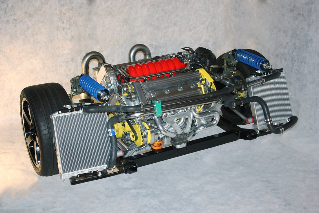
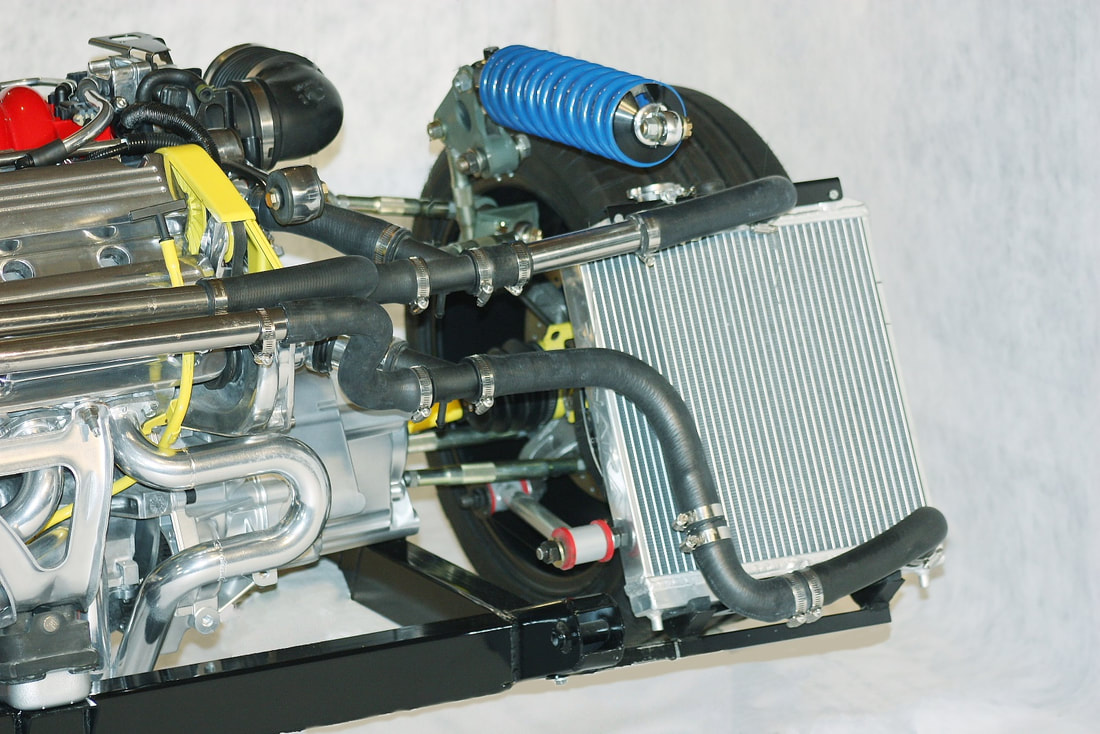
At a later point in this project, I removed the cradle complete with the engine, transmission, and suspension. I then took the time to mock up the powertrain including the cooling system to better show how the system is laid out. These next few photos should clarify the radiator plumbing if there were any questions left unanswered:
At a later point in this project, I removed the cradle complete with the engine, transmission, and suspension. I then took the time to mock up the powertrain including the cooling system to better show how the system is laid out. These next few photos should clarify the radiator plumbing if there were any questions left unanswered:

 RSS Feed
