In my previous post I decided that 4-into-1, long tube, equal length, 180 degree headers were my ultimate goal:
-Long tubes to decrease the backpressure on each cylinder;
-equal length to create synchronized exhaust pressure waves; and
-180 degree construction to maximize the scavenging effect of synchronized pulses... and because they sound incredible too! (Oh... and because my friend Graham is thinking about doing this too and I want to beat him to the punch.)
Having already determined that the best primary tube diameter for my engine would be 1-5/8", the next step was to calculate the optimum length of the primary pipes, at least theoretically. There are several different formulae to calculate the ideal length for a primary tube, but I used this one:
Optimum Primary Tube Length = [(850 X Exhaust Duration) / Peak Torque RPM] - 3
Plugging in my LD8 model Northstar engine's exhaust cam duration, and my desired 5000 RPM tuning point gave me the following:
= [(850 X 244) / 5000] -3
=38.5" (as measured from the back of the exhaust valve).
| Of course this length is optimized for a straight pipe, so any bends in the primary tubes will change the velocity of the gases, and ultimately change the effective length of the tubes too. This next illustration shows the changes in velocity of a gas in a typical 180 degree, mandrel bent tube. The middle green colour (1) is the average velocity, the darkest blue areas are 1/10th the average speed, and the reddest gases are flowing 1.8 times faster than average. These changing velocities affect the timing of the exhaust pulse's arrival at the end of the pipe. | 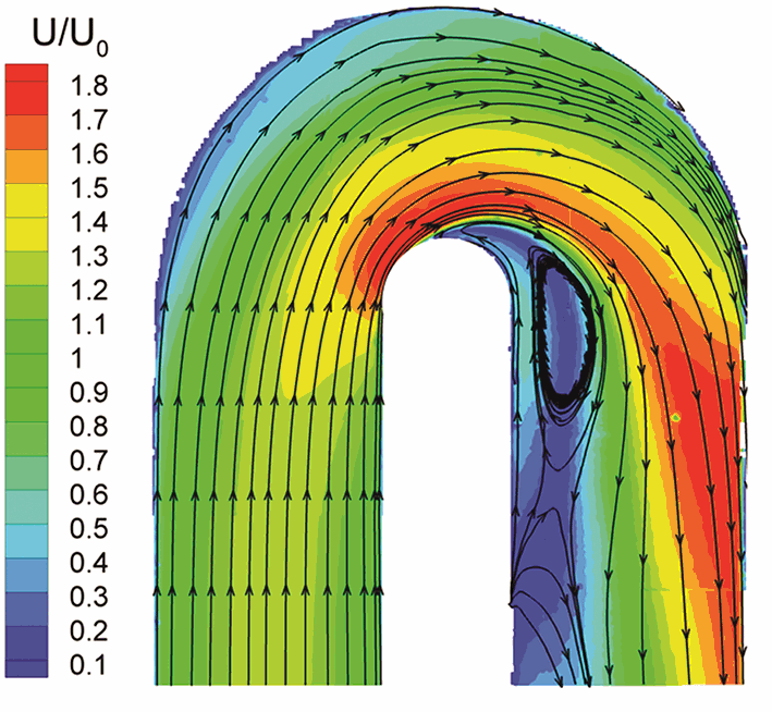 |
Bends or not, the scavenging effect of a 38" primary pipe will be improved over an unequal length system, where the difference in pipe length can be as much as a foot or more.
At this point, I had everything I needed to start playing around with physical layouts: a defined pipe diameter, an optimal pipe length to shoot for, and $100 worth of ABS plastic sewer pipe.
The most logical place to begin was at the forward cylinder head. Since these tubes were the greatest distance from the rear of the chassis, one of them would end up being the longest of all, and it would ultimately define the required length of all seven remaining tubes. Here's the empty canvas:
To get at least some of the pipes to the other side of the engine, I planned to make use of the OEM notch between the oil pan and transmission. Then I discovered an added benefit to having redesigned a wider engine cradle. A second tunnel was formed at the front end of the engine too! (Note that the drawing below is flipped as compared to the photo above.)
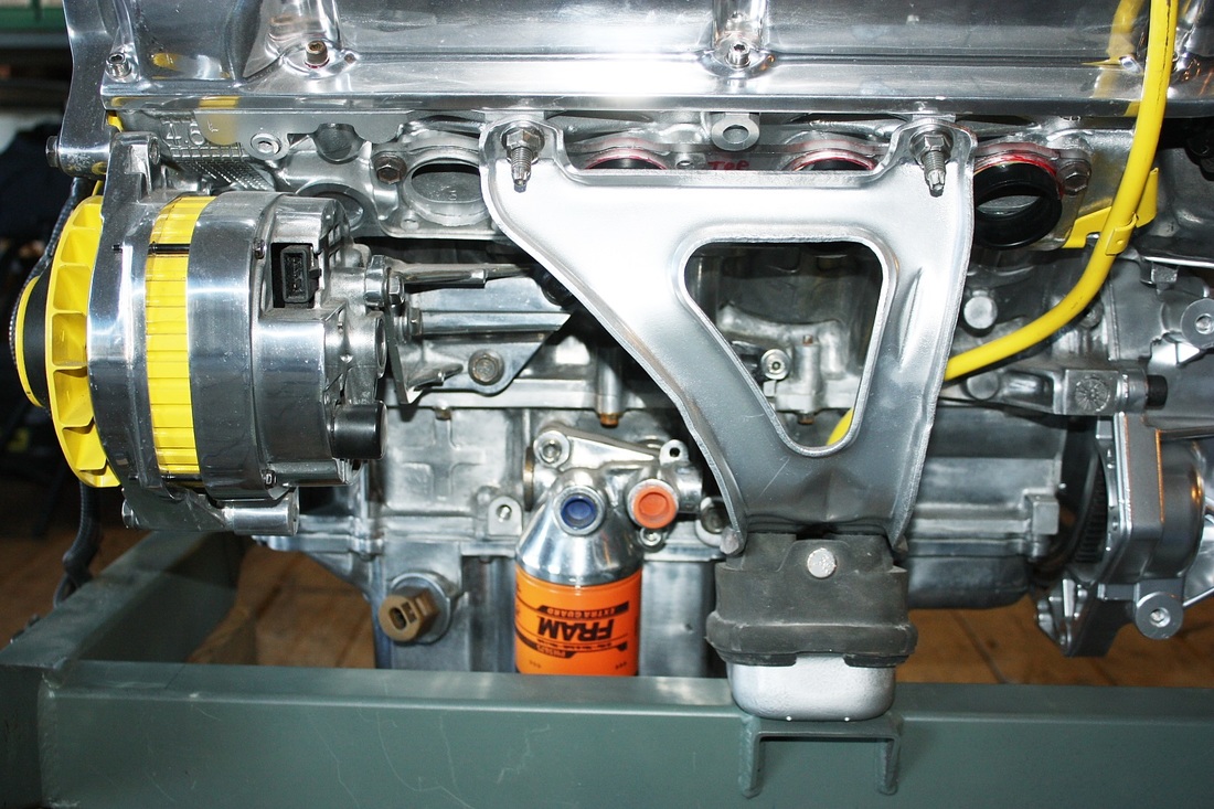
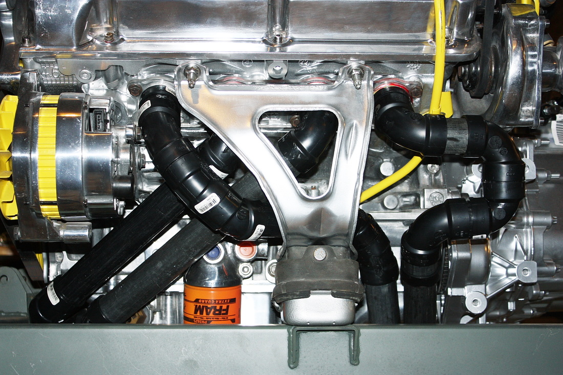
One issue solved, three others to overcome: On this forward side of the engine, the oil filter, alternator, and engine mount all conspired to make my life difficult by cramping the area. Here's the side view of the engine mount showing the space available between it and the engine block... it was pretty compact for four pipes!
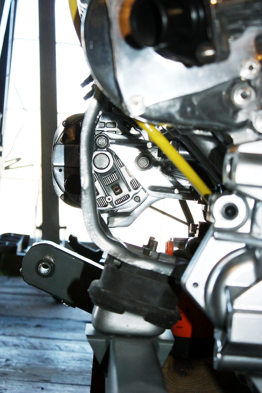
Lastly, I had to consider how to incorporate the 180 degree aspect within this space. To do this, I had to pair the two outer exhaust ports together and the two inner ports together at some point. That meant I had to cross one of the tubes from an outer exhaust port over (or under) the two tubes from the inner ports. The location where they crossed over could be done in one of two places: either before tunnelling under the block, or after. This second option is what I initially tried since it was aesthetically pleasing and made plenty of room for the oil filter, crank sensors, and oil level sensor. Here's how it looked mocked up on my spare (dirty) engine:
It was only later that I discovered it wasn't a great idea, for two reasons. Crossing the tubes inevitably requires more tube length, which takes up additional space. Once I started mocking up the primary tubes on the aft cylinder head, I found space to be at a premium. The axle shaft, and two engine mounts were very confining.
The other reason was that I simply couldn't find a way to route all the tubes without one of them (and therefore all of them) running 58" long! It appeared as though a decent 180 degree system might not be achievable by running the tubes under the engine. I had seen several examples where others had run the pipes over the transmission, but I didn't like the aesthetics, nor the idea of all that heat so close to fuel lines, and shifter and accelerator cables.
So I started from scratch again (the benefit of my ABS Lego set!), except this time rather than crossing the outer port's tubes on the aft side of the engine, I did it before they entered the tunnels under the engine:
Not quite as visually elegant, at least from this side, but it made a helluva difference to the overall length and space for the remaining seven tubes. Total length of each tube: 38 inches plus or minus a half inch. Perfect!
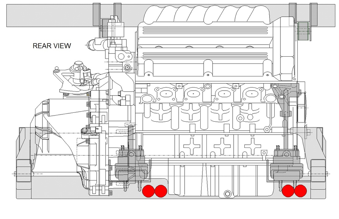
Here's a schematic showing the layout more clearly:
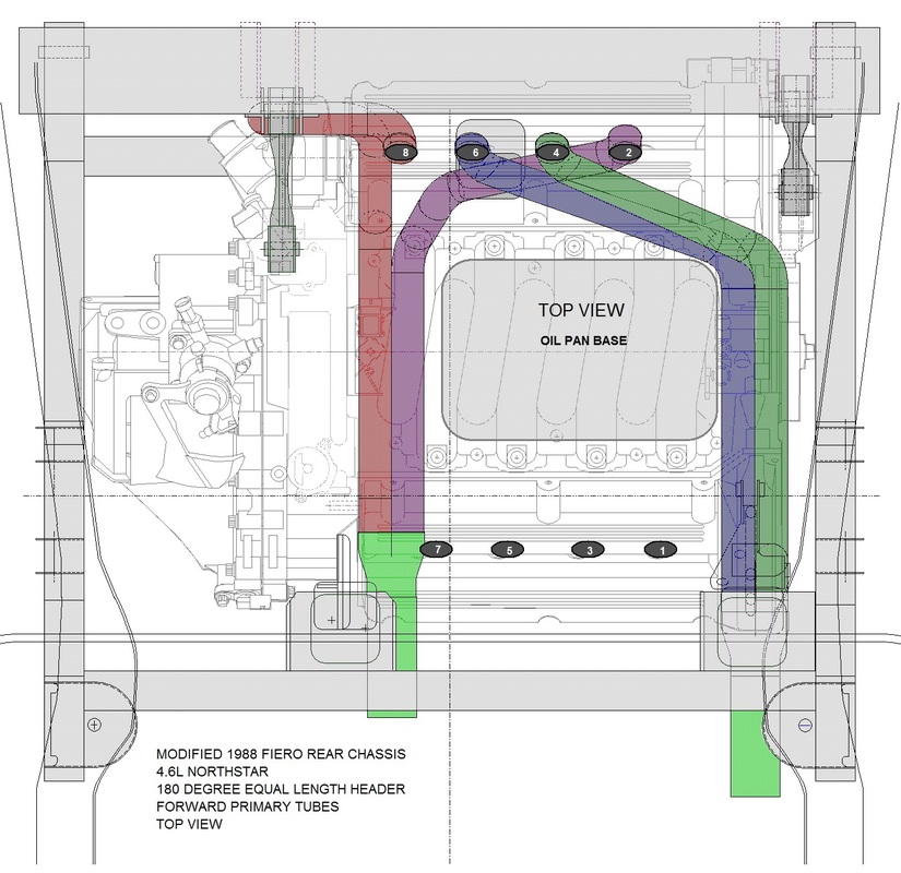
Of course they don't look the same length in this top-down view but that's because you can't see the height dimension. It was difficult enough to draw this view that I decided not to draw the side and rear views... pictures will have to suffice! The other nice thing is that the outlets of the two pairs are staggered. This will allow a staggering of the mufflers and catalytic converters for each system.
Next up: the aft cylinder head's primary exhaust layout.

 RSS Feed
