Designing the layout of the aft primary tubes was more challenging than it was for the forward cylinder head. I already knew the start and end locations of each pipe and I also knew how long to make them, but it took me three full blown attempts to get them right.
Finding non-intersecting paths for the four pipes within the confines of the cradle was the challenging part. Clearly most tubes would need to head away from their final destinations and fold back over themselves to make up the total length required to match their counterparts from the other side of the engine. The jackshaft and inner tripot joint cramped the room towards the front, the transmission mount and aft engine mount confined the space sideways, and the rear cradle crossmember defined the space to the rear.
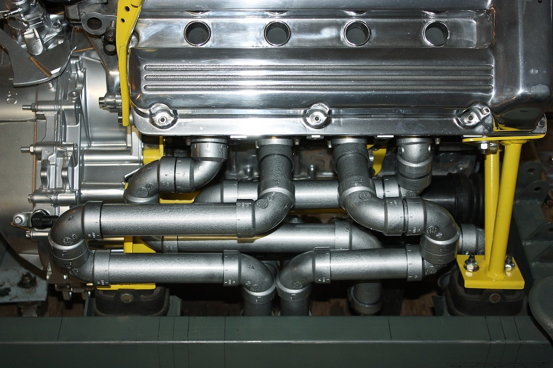
I finally decided on this layout, which I found pretty clean and appealing:
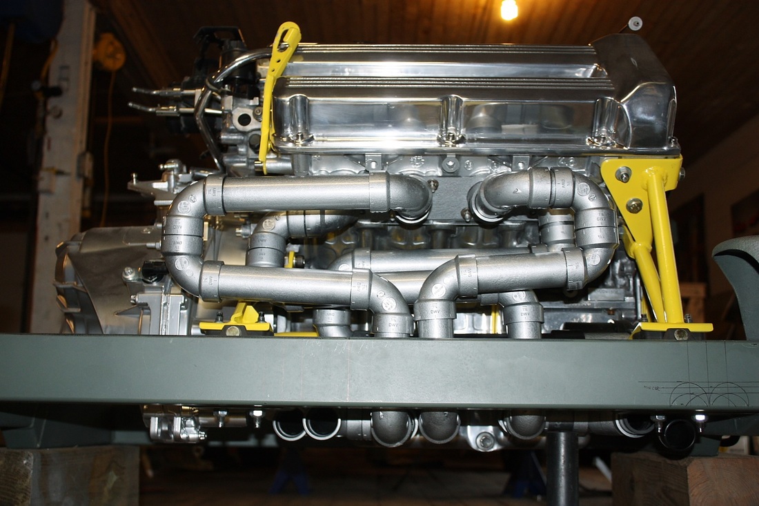
One nice thing about my redesigned the cradle was that I had kicked up the rear side rails and mounted the rear crossmember higher in anticipation of passing the exhaust pipes under it. Here's the rear view:
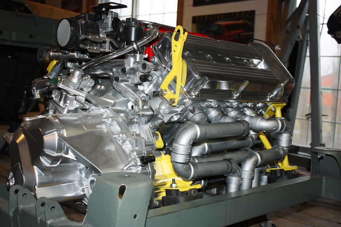
It's certainly a convoluted design with at least one 180 degree U turn and a couple 90 degree elbows per pipe. Here's the 3/4 view from the driver's side:
As with the forward pipes, I didn't even try to draw the layout in advance. I can't imagine how anyone could visualize this type of 3D maze, draw it in advance, and get all the right lengths in less time than it took me to physically mock it up.
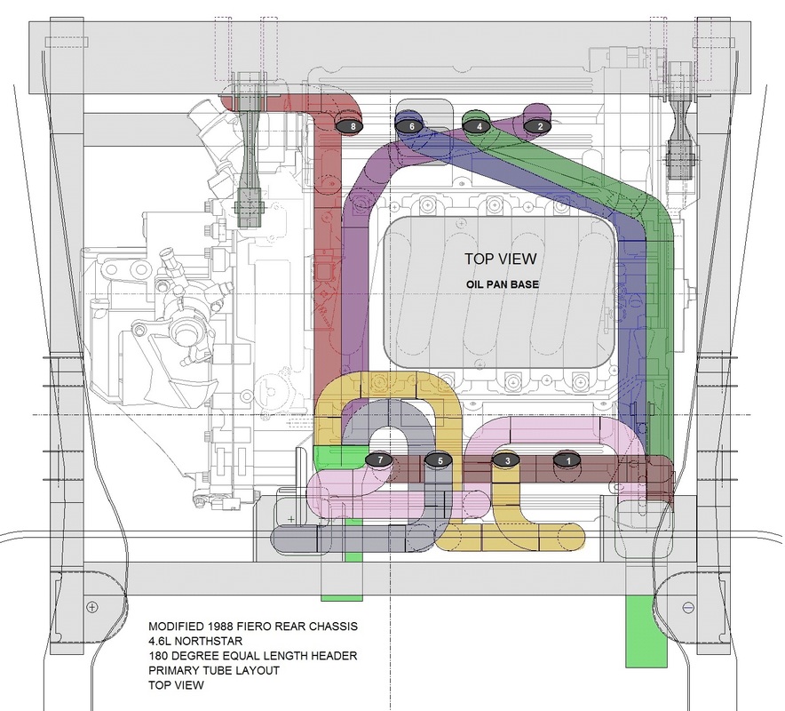
Here's the top view of the aft pipe configuration. I've added makeshift collectors in bright green just to aid in the visuals for now:
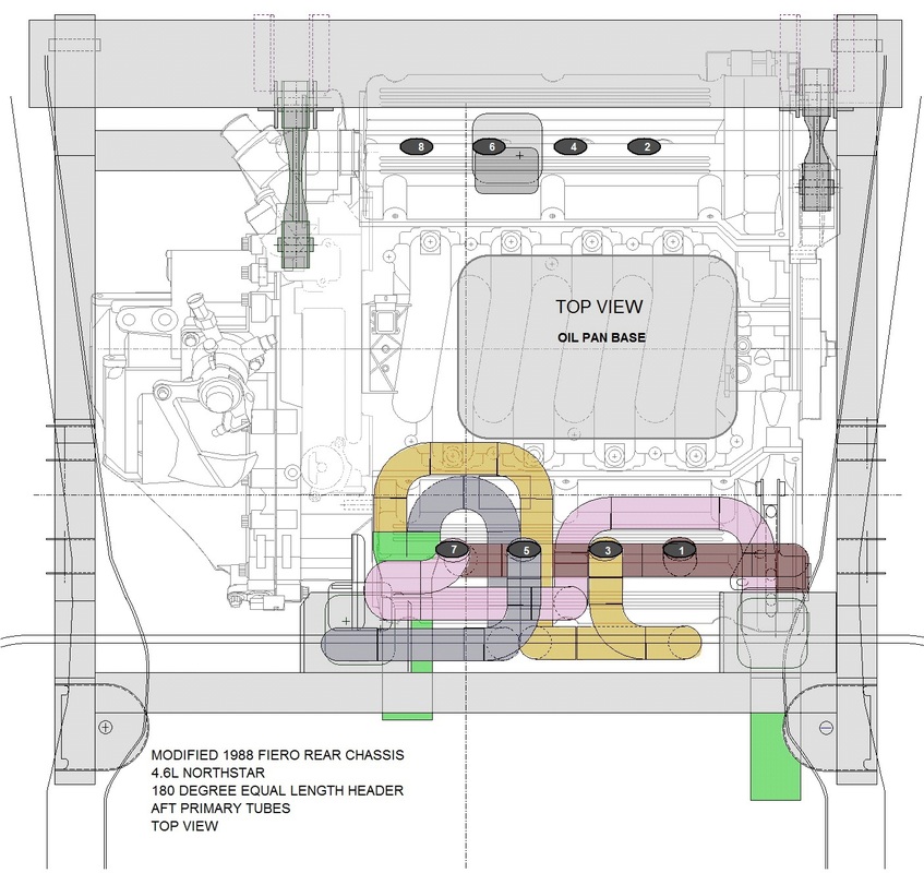
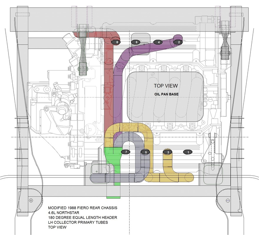
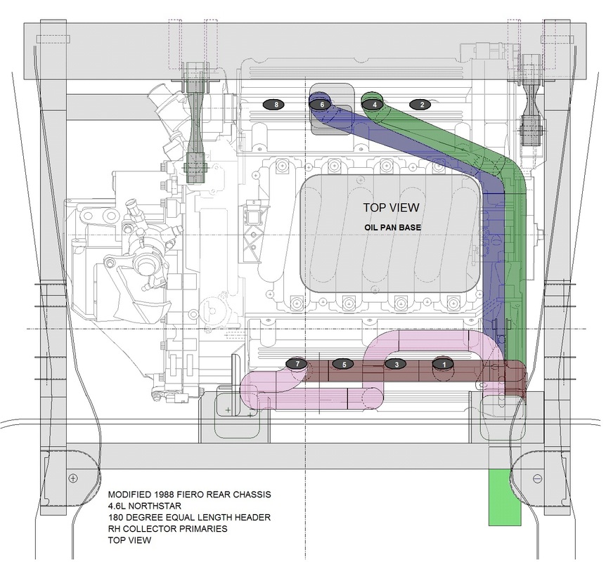
To more clearly illustrate how the two 4-into-1 circuits of the 180 degree header design dump into their respective collector tubes, check out the following two schematics:
And here's all of them together on the same drawing:
Next up is figuring out the rest of the system.

 RSS Feed
