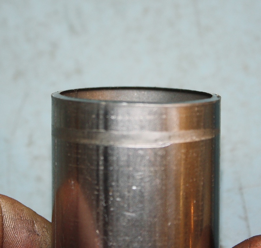
With my blueprints in hand, I got the pipe cutter oiled up and the chop saw freshly aligned. One of the little details I was a stickler about while cutting the pipes was to ensure a smooth transition on the inside of the pipes at each joint. In the photo below, if you squint hard, you'll see that the pipe cutter leaves a ridge curled inwards:
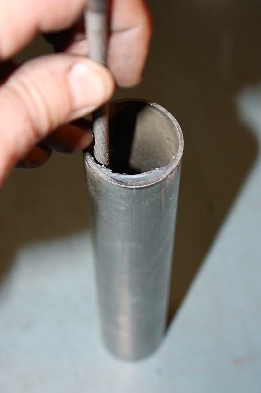
Much worse was the left-over flash whenever I used the chop saw:
I painstakingly hand-filed the ridges and flash on the inside diameter of each cut, then squared each joint on a bench mounted disk sander, and finally bevelled the outside diameters for stronger weld seams. There are upwards of 50 joints, each with two pipe ends to dress.
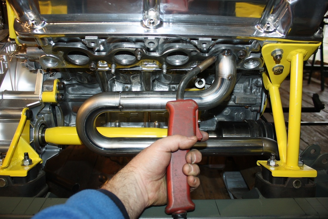
Once the sections for cylinder #1 were ready, I tacked the pieces together, aligned the snake on the engine and tacked it to the exhaust flange:
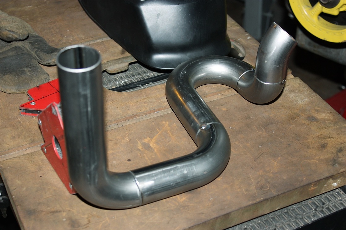
Even though I had plenty of experience by this time, it still took me two to three hours on average to triple check the measurements, cut, prep, align, tack weld, test fit, and adjust the joints to fabricate a complete tube. It's simple, but very tedious if you want the pipes to be straight and level, and have perfect joints. Here's the tube for cylinder #3 nearing completion:
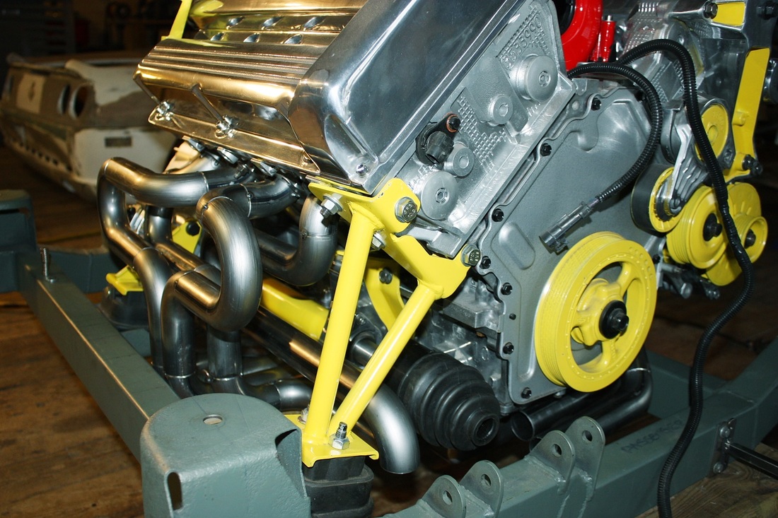
A couple days later I finally understood why custom headers can be pretty expensive. I've kept track of my hours but I'm afraid to tally them up! Here's the overall view of the nearly completed aft cylinder head primary tubes:
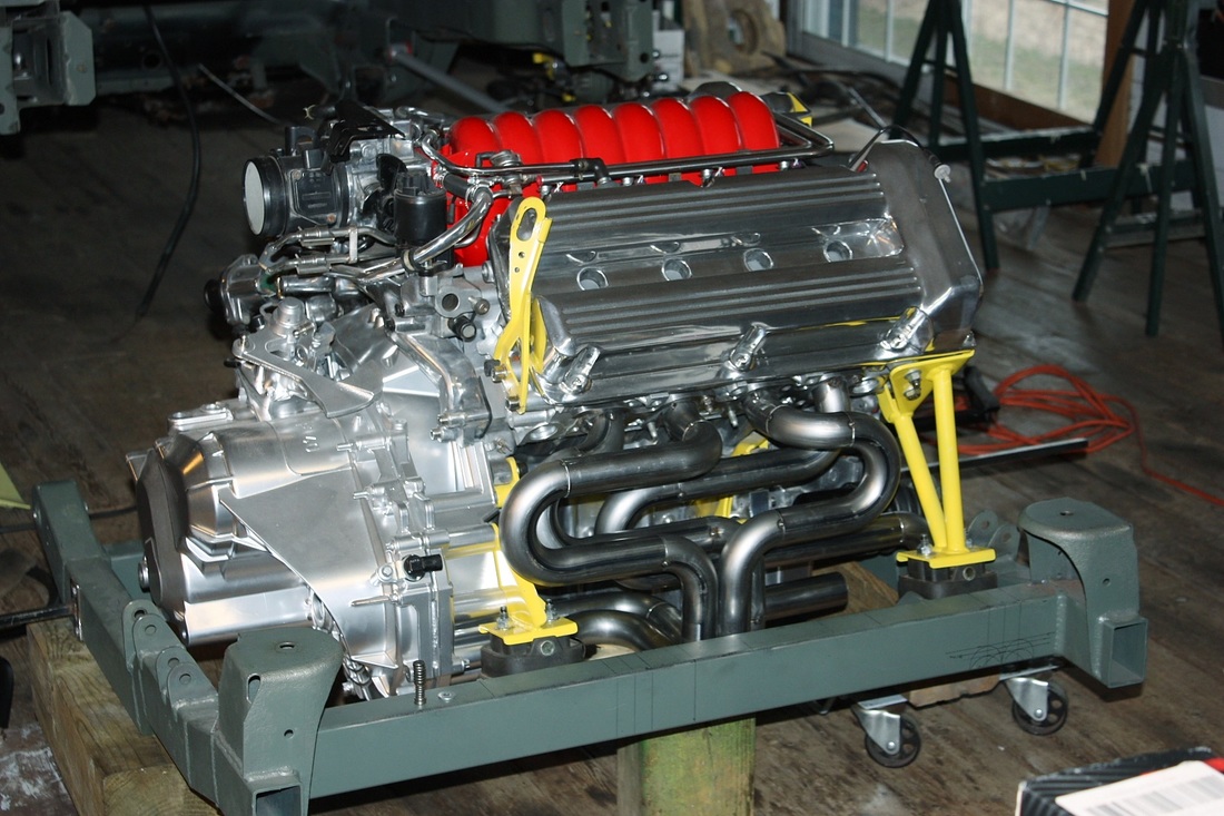
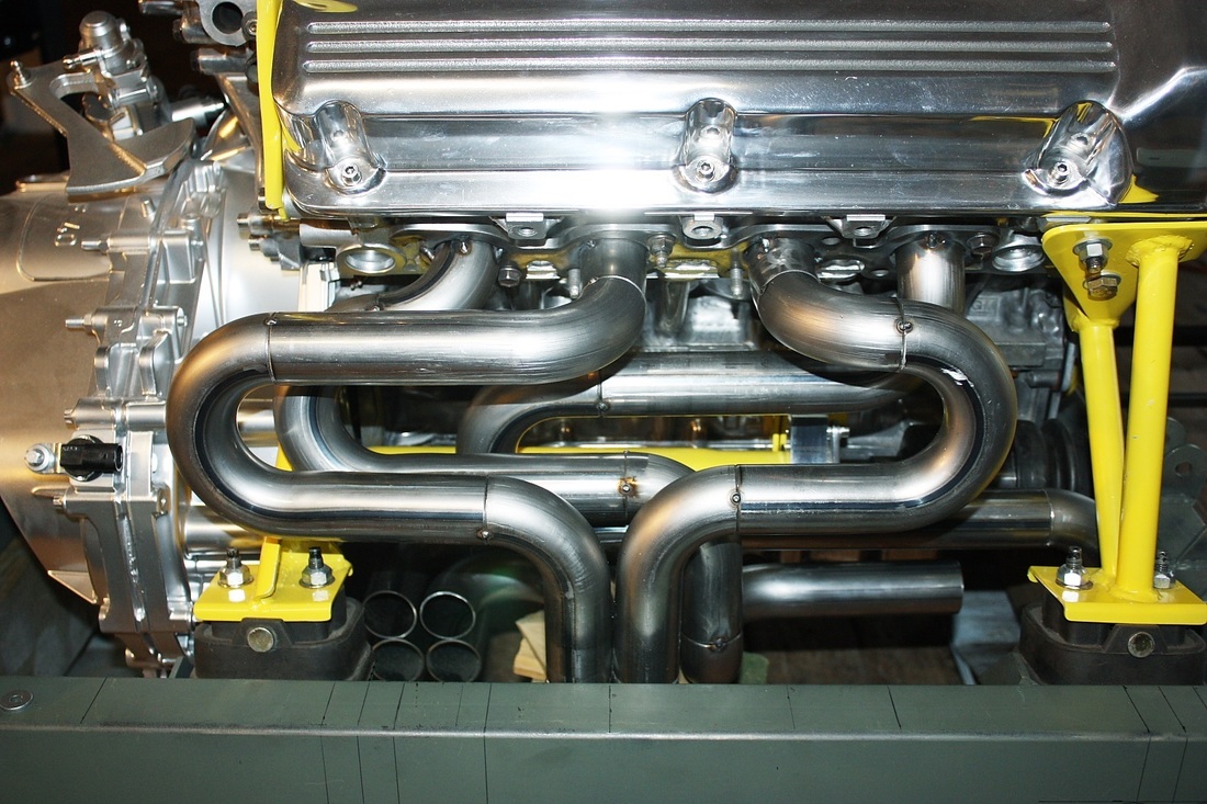
I'm pretty satisfied with this layout from an aesthetics stand point. I kept all of the tubes inside the confines of the cradle, and the tubes follow similar or mirror image paths in many places:
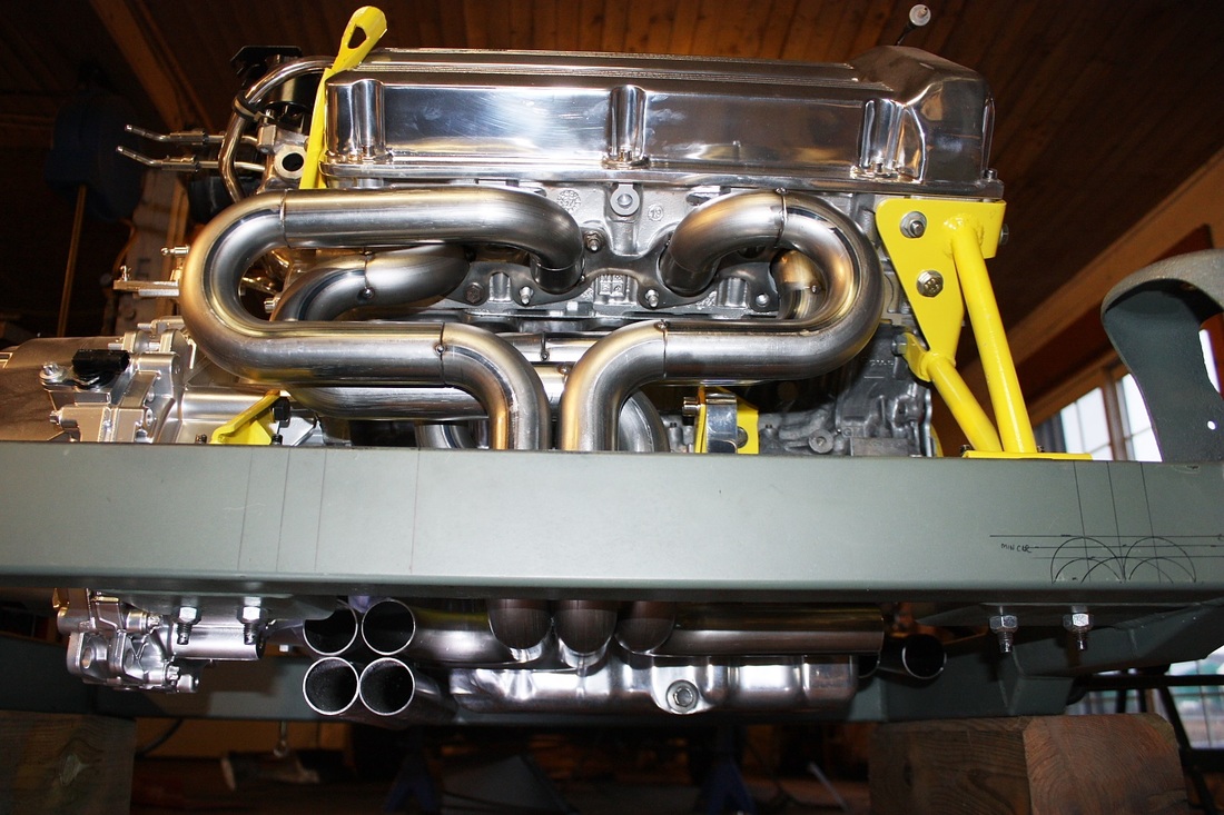
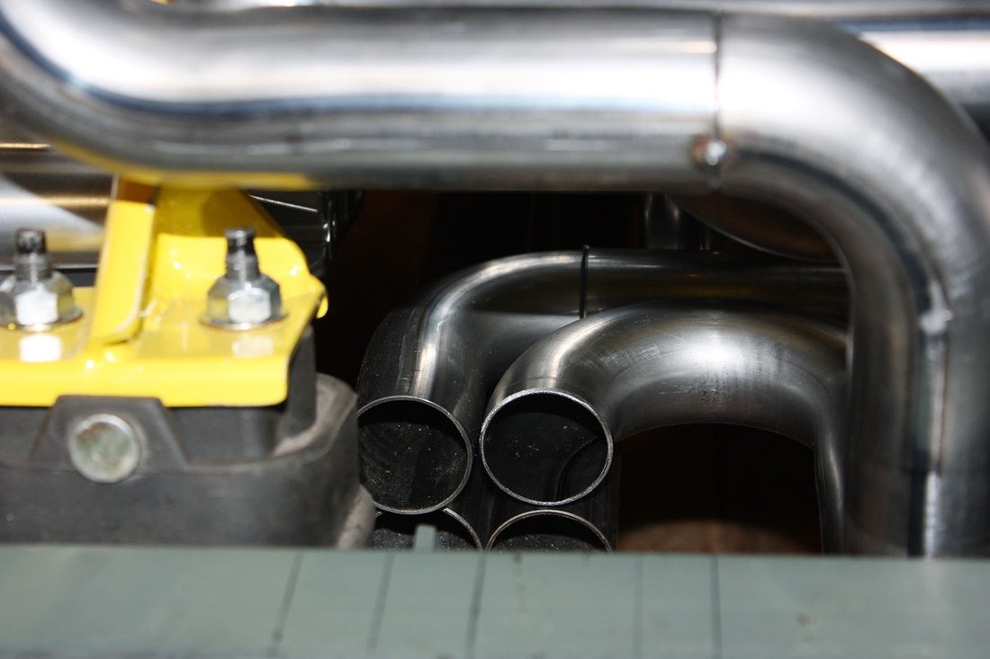
Here's a worm's eye view showing how three vertical tubes converge in the middle, head towards the engine, then splay off in opposite directions. In this photo only the LH group of four pipes is complete:
I couldn't complete the RH group of primary tubes just yet because I came across a challenge I mentioned earlier about having to raise the engine mount. Here in this next photo you can see three of the RH pipes while the fourth is hidden by the cradle cross member:
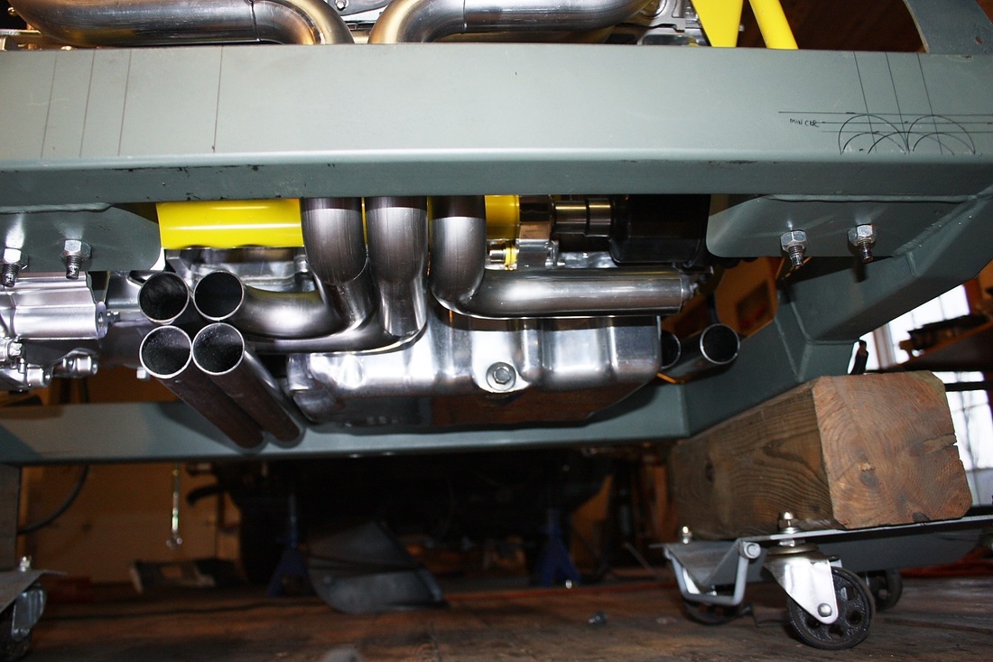
Here's the fourth tube running parallel to the jack shaft. It still requires a 90 degree bend to face aft, but the engine mount is in the way:
You'll also notice the proximity of the CV joint boot to all the exhaust pipes that converge under it and behind it. I'll probably look into fabricating a cylindrical shield to protect it from the heat.
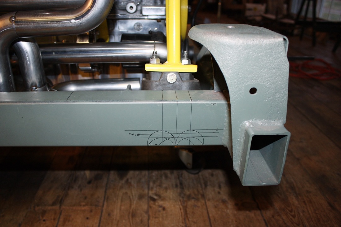
The engine mount bracket is currently flush with the bottom edge of the cross member. I'll need to raise it about halfway up the height of the wall, and notch the crossmember in order to pass the collector under it. These chicken scratchings show some dimensions I was playing with:
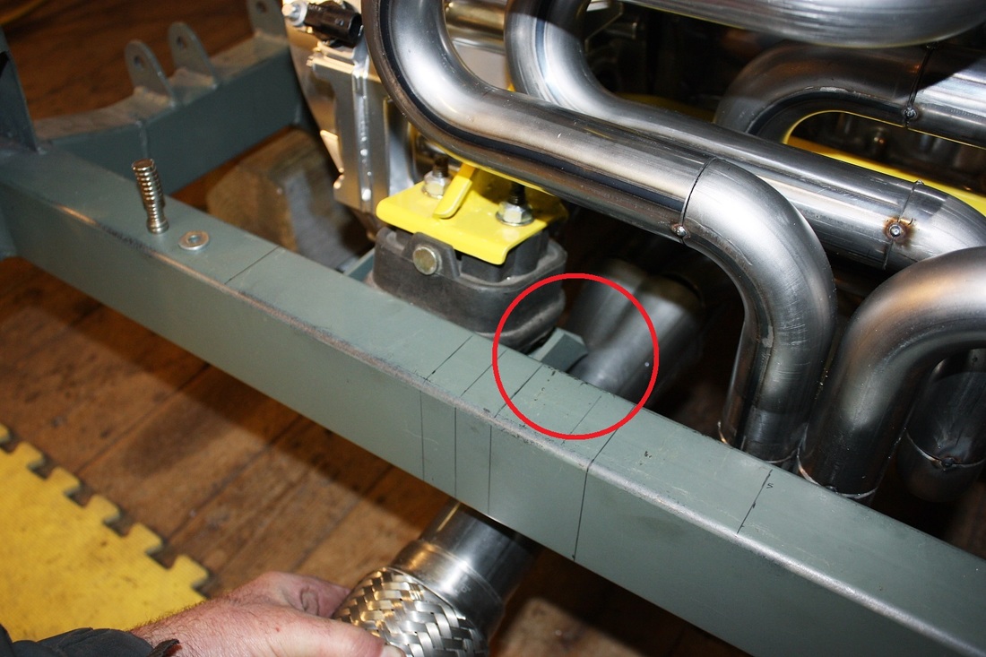
Meanwhile on the opposite side, the LH collector pipes come pretty close to the transmission mount.
While the primary pipes don't interfere with the mount, the collector will. I'll have to modify the transmission mount and make a notch in the cradle cross member, although I'm sure I can get by without having to raise the mount. I'll be certain to account for movement of the engine as well:
Now that I know exactly where to notch the cradle, I'll pull the engine off, make the changes, and make a trip to the paint shop with it. Then I'll be able to finish up the rest of the exhaust system.

 RSS Feed
