The publishers of Stephen Hawking's best seller "A Brief History of Time" told him he'd lose a million book sales for every formula he decided to keep in the book. In the end, he removed them all. I sometimes feel the same about the number of paragraphs in my blog... (Just the pictures please!) So I apologize in advance for this post because it's going to be wordy. Not so much for you, the reader, as it is to remind me why it took me 20 years to build a simple kit car.
In this post I'm tackling two related issues that have nagged me for quite some time. One is the design of the IFG fibreglass roof, and the other is the rear storage area (trunk). Luckily I've had all summer to think about them.
To backtrack for a second, I discovered how remarkably well-suited the lowered and stretched Fiero chassis really is for the F355 replica. Here, I've taken a side view drawing of my modified chassis and superimposed it on a photo of an authentic F355. I matched the sizes of the two images by locking the aspect ratio of both images and scaling them until the wheelbases of the two cars were the same. The similarities are incredible:
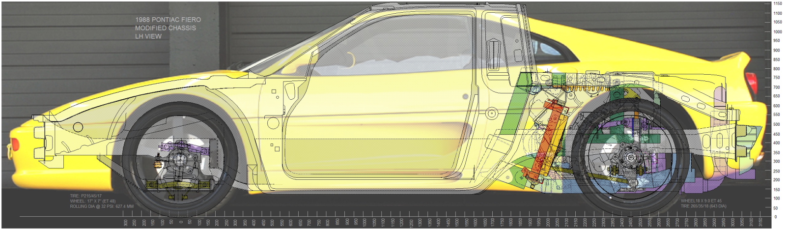
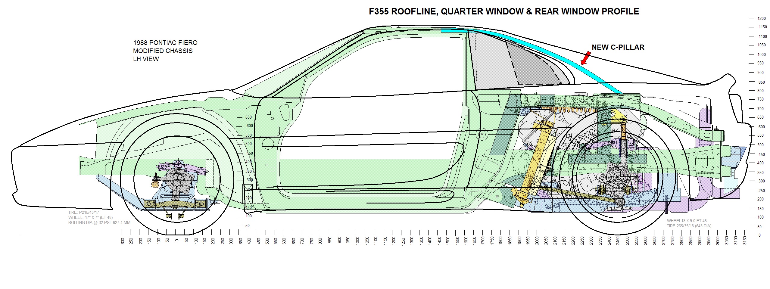
The only real differences are the bumper heights, windshield rake, and the roofline profile and height. IFG designed the fibreglass roof profile so the homebuilder wouldn't need to make structural changes to the Fiero metal roof. To do so, their fibreglass roof followed a much flatter, taller profile, up to the rear roof edge, and then used taller, steeper flying buttresses. To minimize the appearance of the added bulk to the buttresses, IFG designed their own, taller profile quarter windows. Compare the roofline and quarter window profiles from the Ferrari illustration above, to this next one showing the IFG profile:
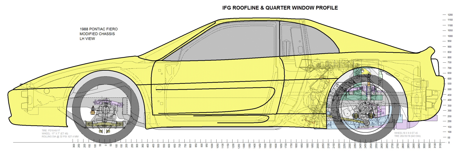
For the average builder, the IFG roof profile simplifies building the kit immensely, but it would never pass scrutiny for Ferrari aficionados. This next photo shows just how much of a difference there is in the profiles of the authentic F355 quarter windows and a template I made for the IFG window:
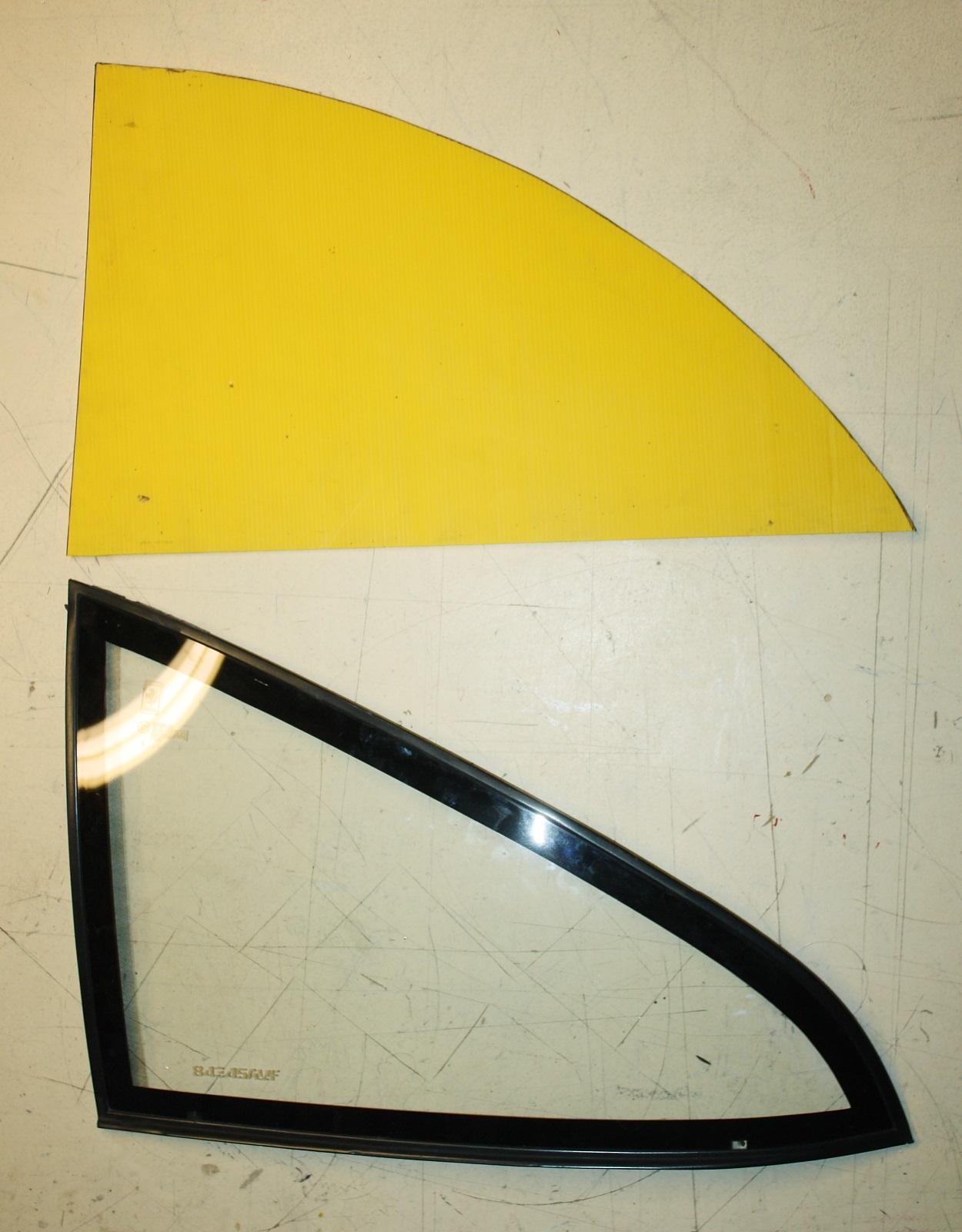
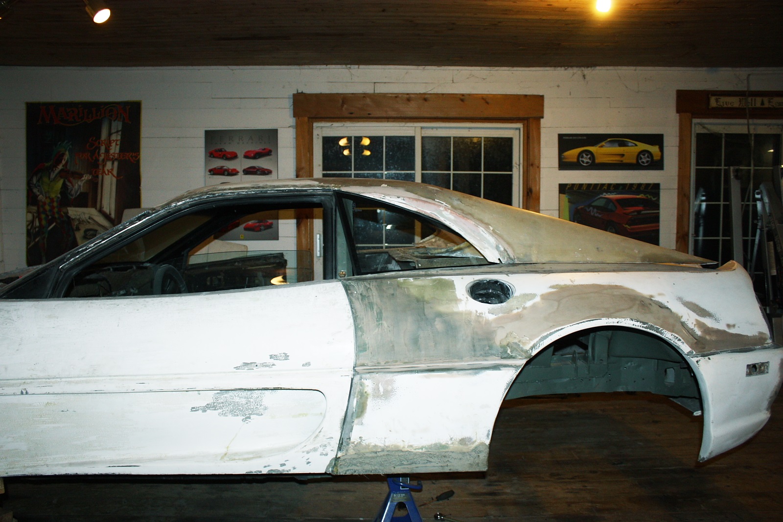
Note how much more rounded the top of the IFG template is. That spells trouble for anyone wanting to use the authentic Ferrari glass. If the buttresses were modified simply by reframing them to fit the Ferrari quarter windows, the buttresses would be as thick as tree trunks. Compare the visual weight of the buttresses on the car in the photo below, to the poster on the wall of the yellow F355 behind it:
My challenge was to make the very expensive F355 quarter windows (I bought them, I'm using them!) look right on the IFG kit.
My first viable idea was to buy the combination roof and buttress panel from the current supplier of the AD355 body kit, which is a stunning replica that happens to use the authentic F355 quarter windows. Their kit requires cutting most of the Fiero metal B-pillar away and bending the aft portion of the metal roof downward to achieve a more authentic profile. Unfortunately, after calculating currency exchange, shipping, customs fees, and taxes, this option was CDN$2000, despite having been offered a reasonable purchase price by the company.
My second option was to cut up the IFG roof panel to accomplish the same look as the AD355 panel. More work on my behalf, but I don't charge myself for labour! Seeing how the previous owner of my car had already chopped and begun to reinforce the B-pillar in much the way the AD355 kit is done, I was already part way there. Here's an illustration showing my chassis as it currently stands, overlaid with the roof and quarter window profiles I want:
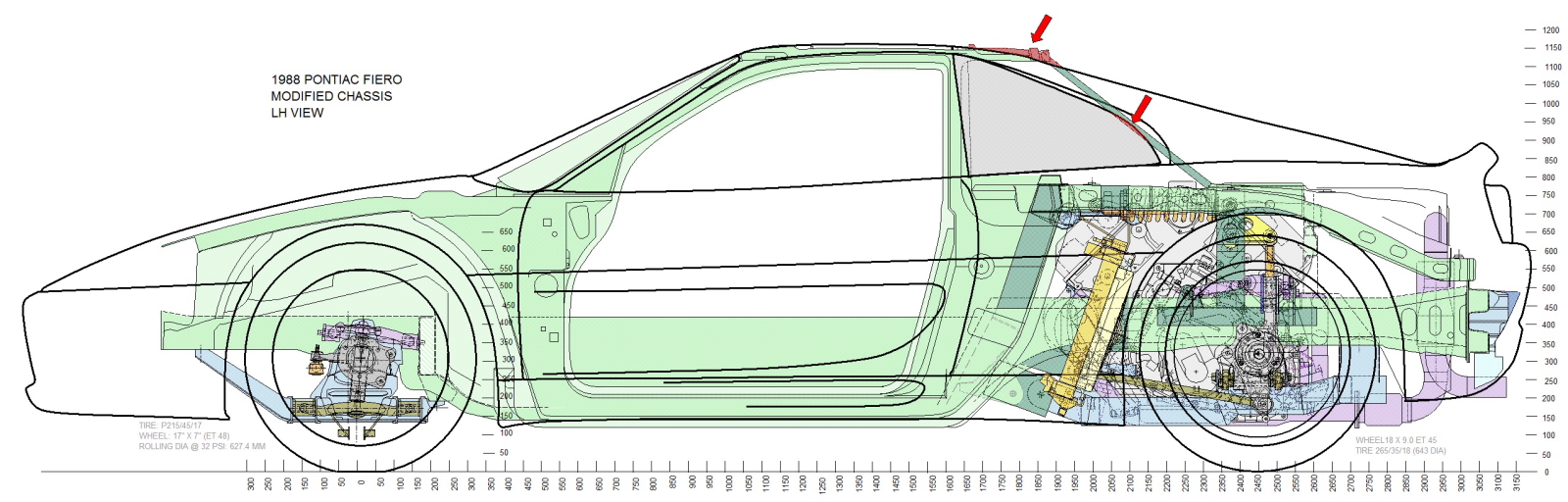
The red arrows show where I still have structural work ahead of me. The structural tubes that were added to make up the C-pillars need to be separated from the roof so it can be given the right slope. The current angle of the C-pillars also makes them encroach into the quarter windows slightly, and would have intruded into the cabin, so they were going to be replaced one way or another. Here's my solution to the C-pillar:
I'll form a section of 1" diameter seamless tube (arrow) and slide the top end several inches inside the OEM roof channel, then rosette weld it into place.
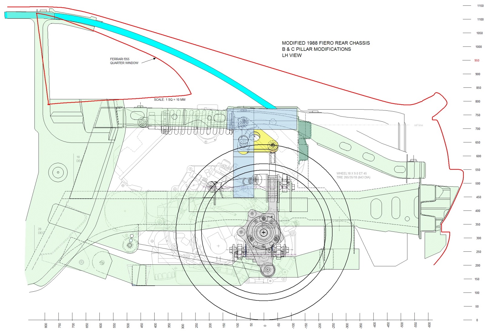
The lower end will be welded to the 2"x4" rectangular steel structure that I previously installed as the main upper anchor point for the suspension bell crank (dark blue in the drawing above). The 1" DOM tube will be entirely hidden within the flying buttress both from inside and outside of the car given its new curvature.
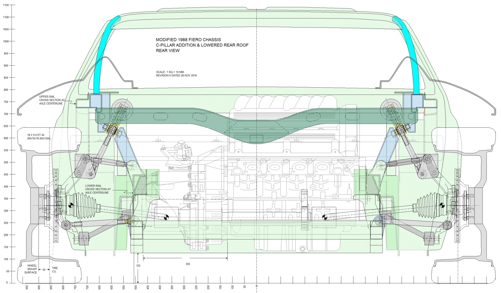
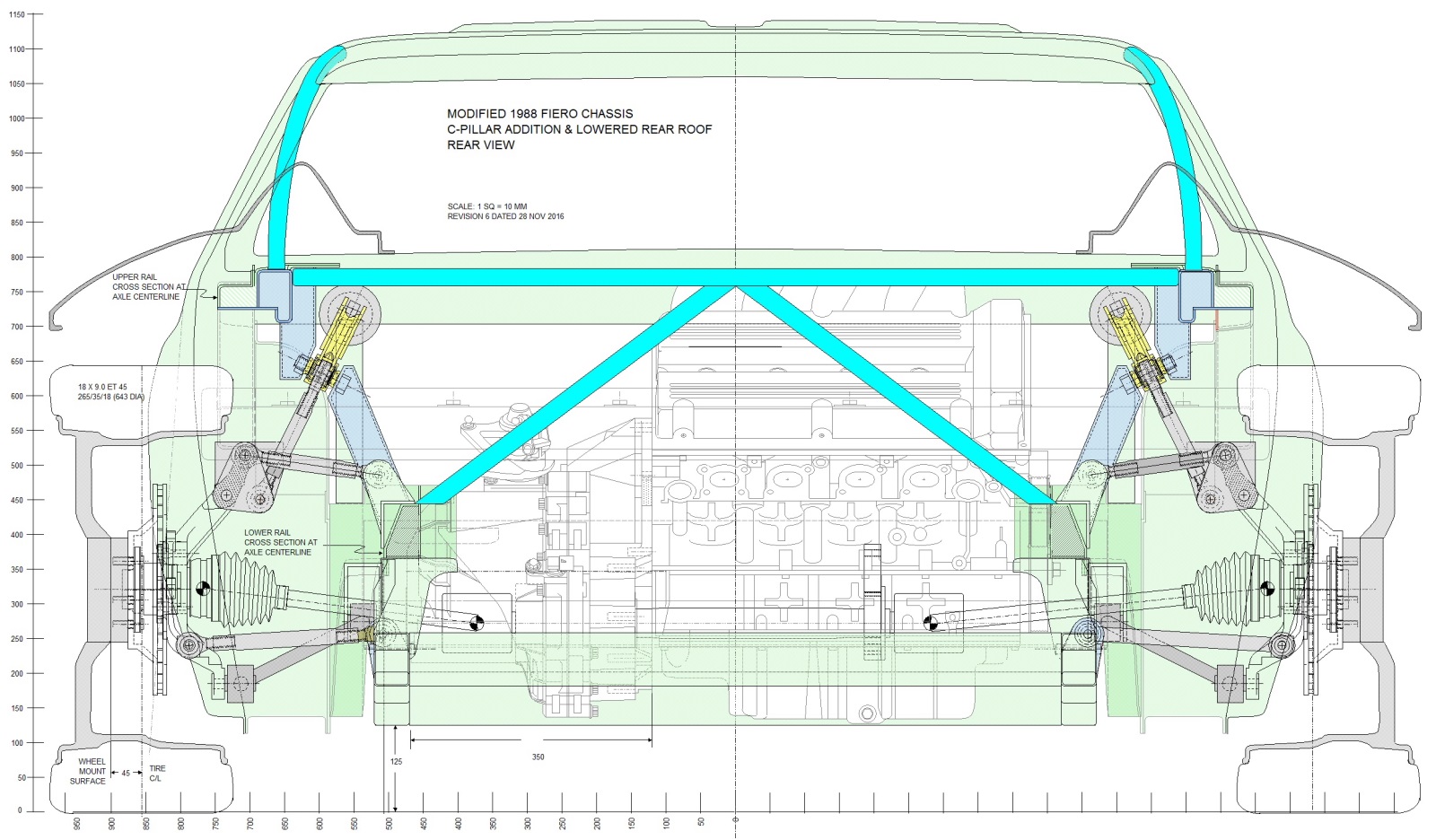
Here's the rear view of the new C-pillar showing the load path from the roof to the upper frame rail, and from the upper rail to the lower rail (blue components). Also note the integral OEM cross-car brace in dark green:
The cross-car brace (formerly a strut tower brace) brings the topic around to the second big issue I needed to sort out: the trunk area. From the beginning, I'd strived to maintain a rear storage area simply because there isn't a heck of a lot of storage in a Fiero to begin with. The real estate back there started getting scarce with the forward trunk wall being clearanced for the valve cover, then the cat-back exhaust system ate into the trunk from the back side, and I have yet to design a cold air intake system, and rear sway bar installation. So, I caved and gave up hope for a rear trunk... there's always the front compartment which will be larger without a radiator.
While I was initially disappointed, I've come to realize there are benefits to eliminating the trunk. Packaging essential systems is the big one, but aesthetics are close behind. Here's the ugly mess of what remains of the forward trunk wall and the integral cross car brace (arrow):
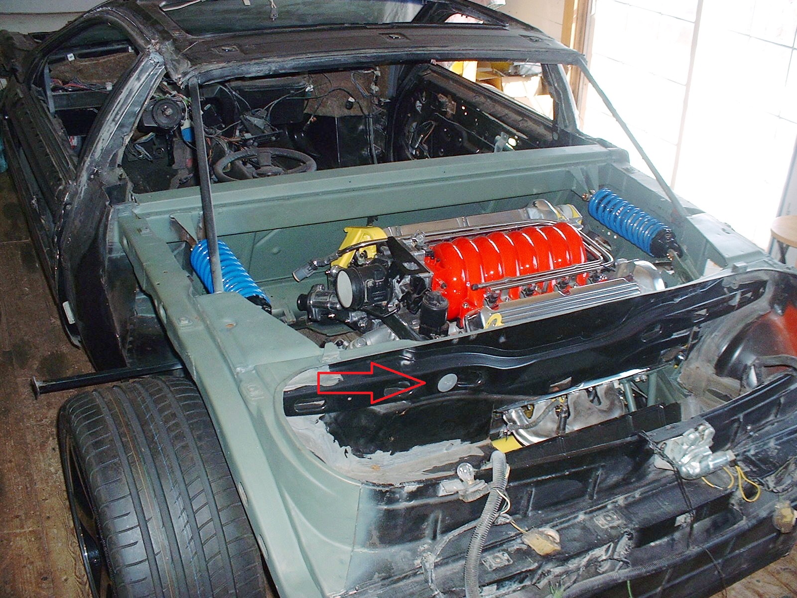
The wall would totally obscure the view of the header system I laboured over. Without the need for a sealing flange around a trunk compartment, I thought I'd trim all the extraneous sheet metal away and leave only the transverse brace. I've seen others do this, and it looks good. Then, while perusing photos of authentic F355 engine bays, I started formulating a new idea. Here's the image of a Ferrari engine cradle that got me thinking:
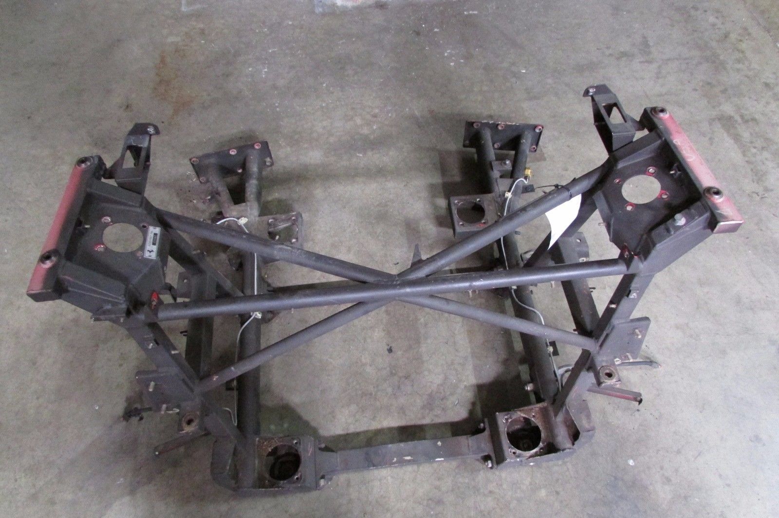
Rather than using a simple cross-car brace, the Ferrari strut towers are triangulated with braces in the longitudinal, transverse, and vertical planes. The braces also conveniently allow clear sightlines and accessibility to the engine and transmission. They also look distinctly Ferrari. Here's how I plan to incorporate the idea into the Fiero engine bay:
I'll use 1" OD seamless round tubing and weld a new cross-car beam between the same 2"x4" upper bell crank mounts as the new C-pillars are welded to. Then, I'll triangulate the cross-car beam in the vertical plane with diagonal braces dropping down to the lower frame rails. Once that's done, I'll be able to remove the forward trunk wall and the old Fiero cross-car brace entirely. That'll open up the sightlines!
This last schematic shows the top view including two additional braces running diagonally forward from the centre of the new cross-car beam, triangulating it in the longitudinal plane. All of the key structures tie into the dark blue bell crank mounts:
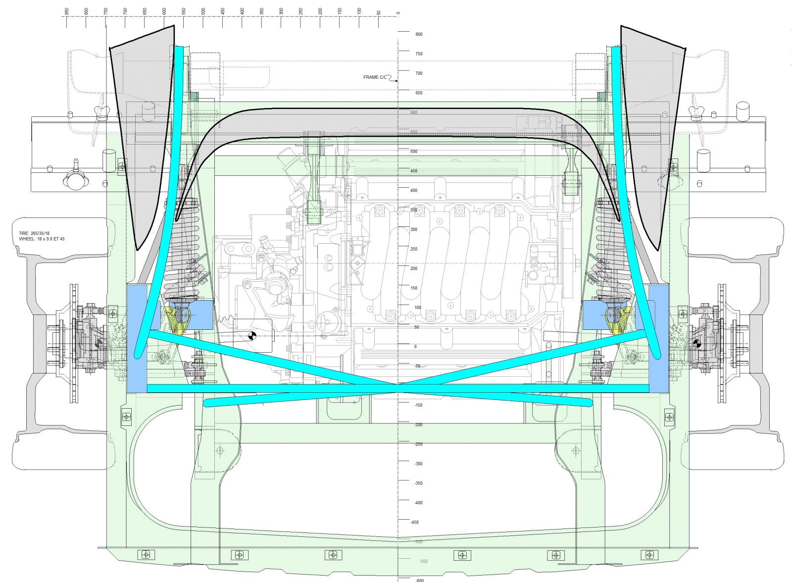
I also threw the quarter windows and the Toyota MR2 rear windshield onto the drawing above to show how they fit in relation to the design of the new C-pillars. I don't plan on installing the windows directly to the fibreglass as many do. Rather, I'll build up a sheet metal framework for each, and anchor the frames to the metal C-pillars. The fibreglass roof/buttress panel will hide the sheet metal work, but that's a story for another post. For now, I've got to order up some 1" DOM steel tubing.
I also threw the quarter windows and the Toyota MR2 rear windshield onto the drawing above to show how they fit in relation to the design of the new C-pillars. I don't plan on installing the windows directly to the fibreglass as many do. Rather, I'll build up a sheet metal framework for each, and anchor the frames to the metal C-pillars. The fibreglass roof/buttress panel will hide the sheet metal work, but that's a story for another post. For now, I've got to order up some 1" DOM steel tubing.

 RSS Feed
