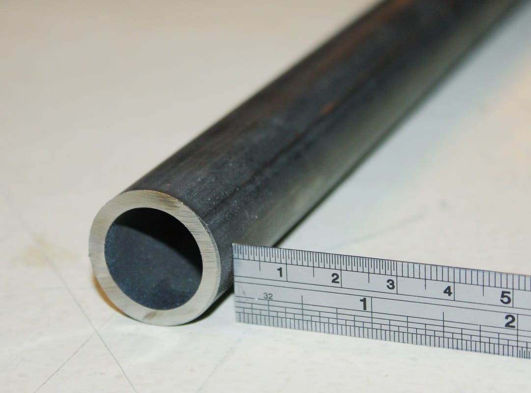
Living in rural Nova Scotia, everything takes its own sweet time to be delivered, and my structural tubing was no exception. When the metal shop called, the price was an unexpectedly cheap $2 per foot, which got my spidy-senses tingling. Sure enough, they had ordered ERW (or electric resistance welded) tubing. The proper 1" dia X 0.120 wall thickness DOM tubing arrived several days later:
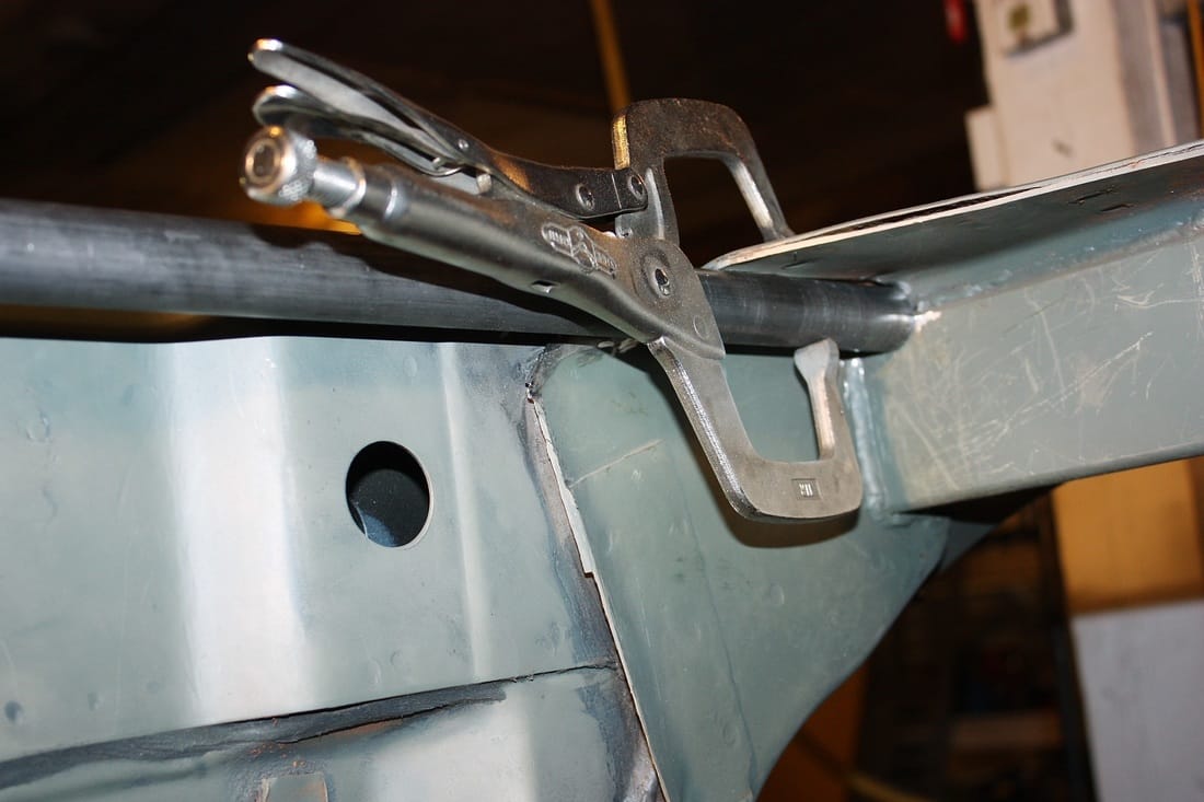
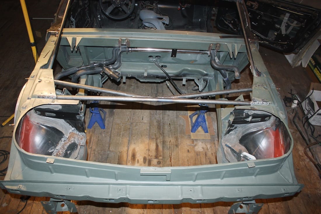
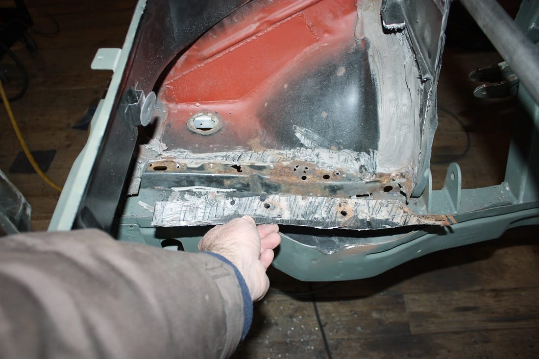
The first length of tubing was cut to 53.75" to fit tightly between the upper frame rails at the back edge of what remained of the strut towers. The photo below is taken from inside the engine bay, facing the driver's side strut tower:
Once the tube was test fitted, it became obvious that welding access would be limited:
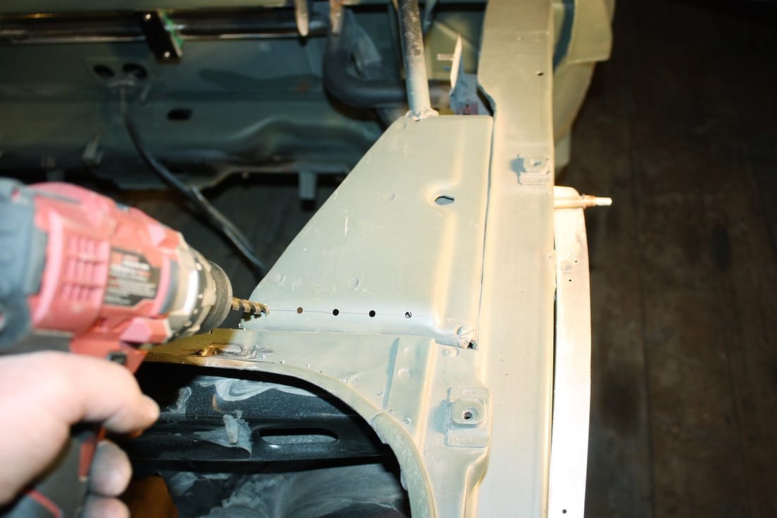
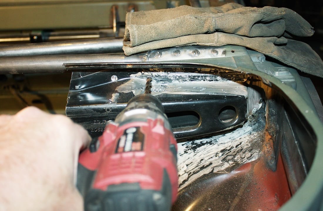
To ensure the best possible attachment of the tube, I drilled holes in the gusset to rosette-weld it to the hidden side. Here I had drilled pilot holes and was enlarging them to 5/16":
Then I rosette welded the main transverse brace into place:
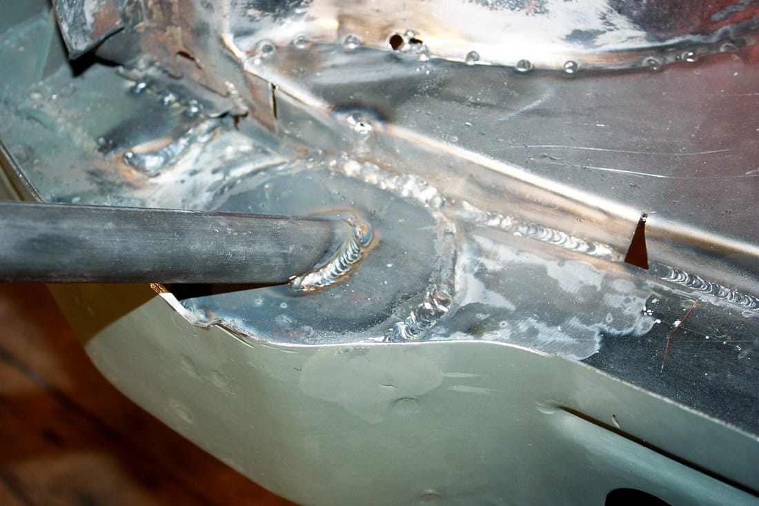
From the engine bay, I bead-welded the transverse brace to the underside of the gusset and the ends to the 2"x4" upper frame rail reinforcement:
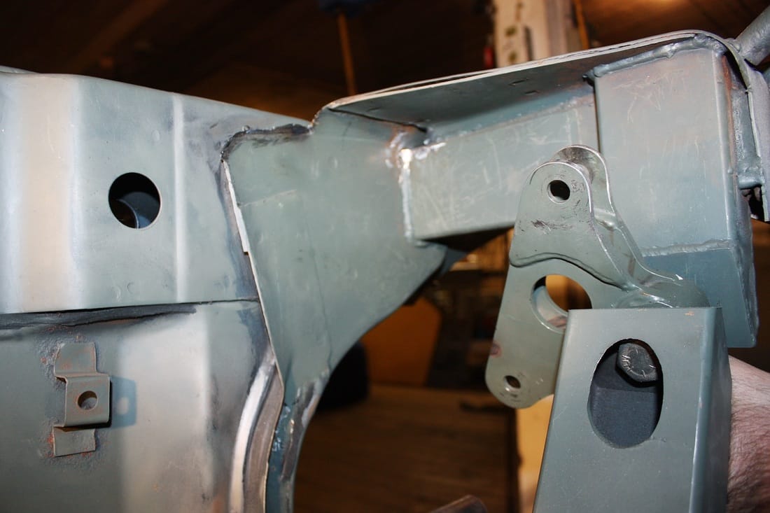
Here's the main transverse tube welded in position:
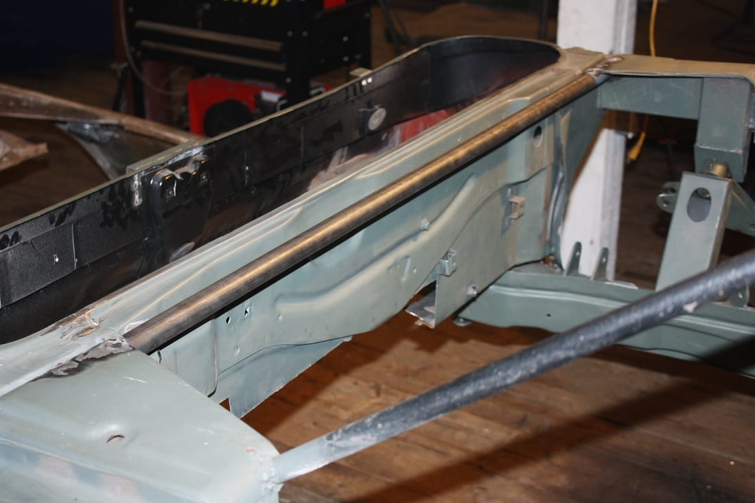
Next came the longitudinal braces. They're positioned to keep the main transverse brace from flexing fore and aft and are attached to the 2"x4" upper frame rail reinforcements mentioned earlier, and to the middle of the transverse brace:
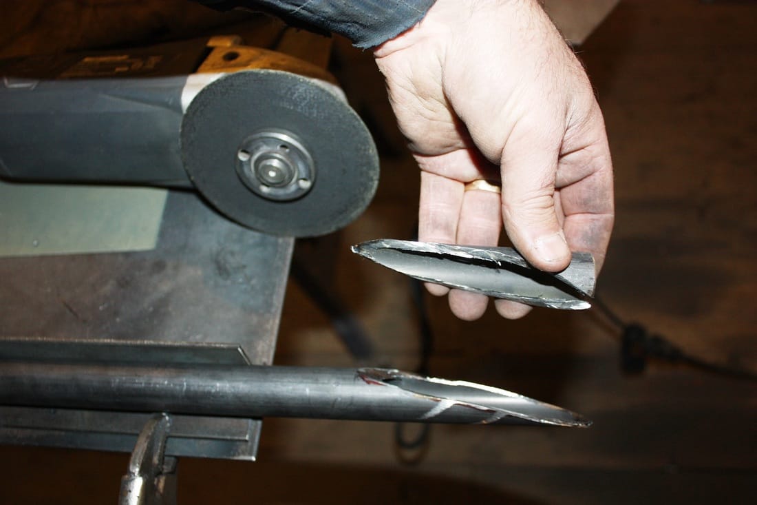
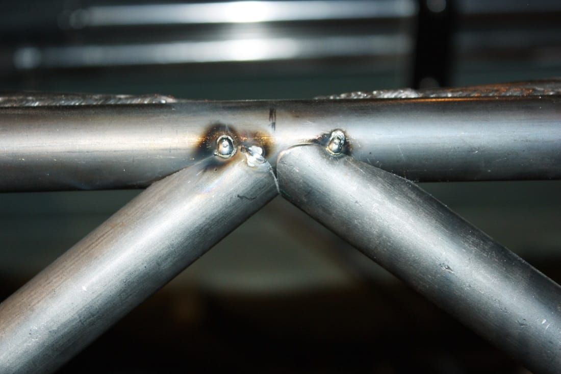
The angle that the longitudinal braces intersect the transverse brace is so shallow, that there was simply no way to jig them up in the drill press to cut a proper "fish-mouth" end on the tubes. A round tube intersecting another round tube is not a simple straight cut. Nevertheless, I resorted to cutting the longitudinal tubes with a cut-off wheel in my angle grinder, then hand shaped the cut with a 1" dia grinding stone to make the mating surface as tight as possible with the transverse tube:
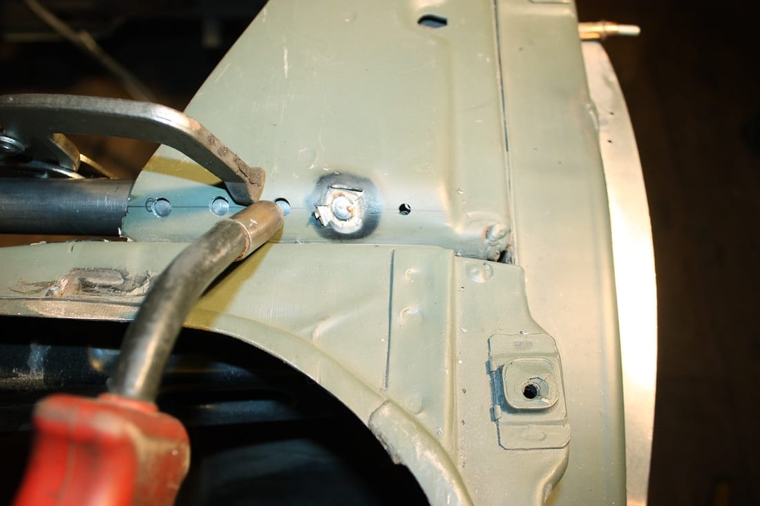
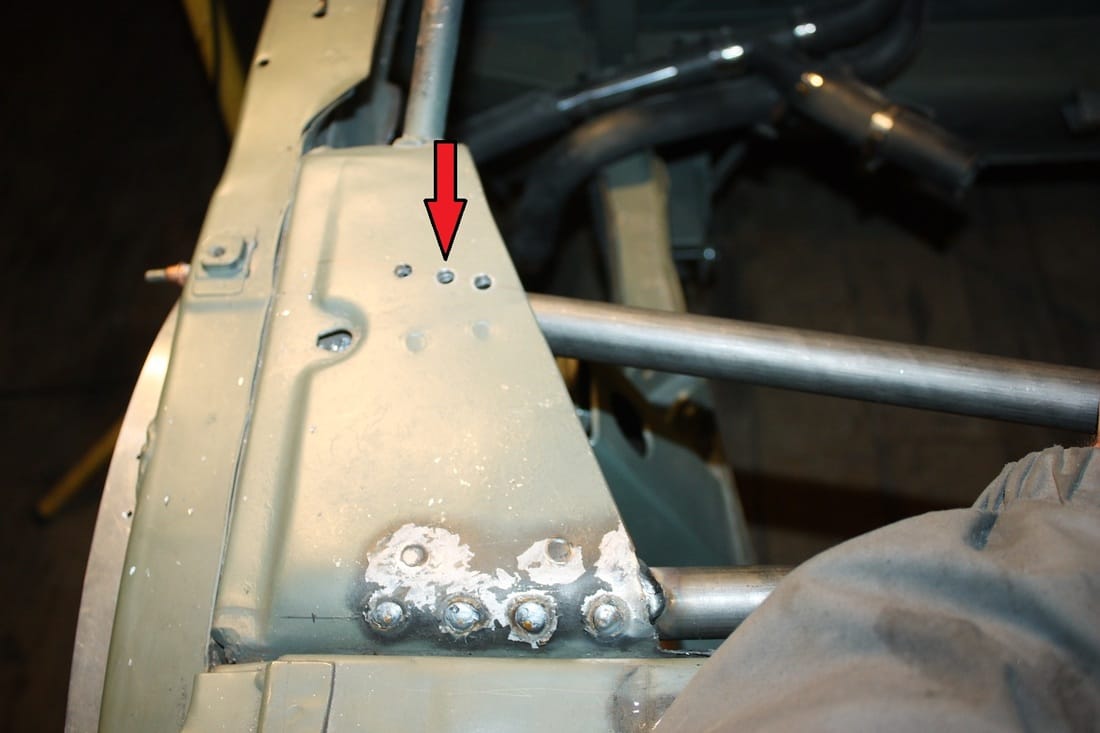
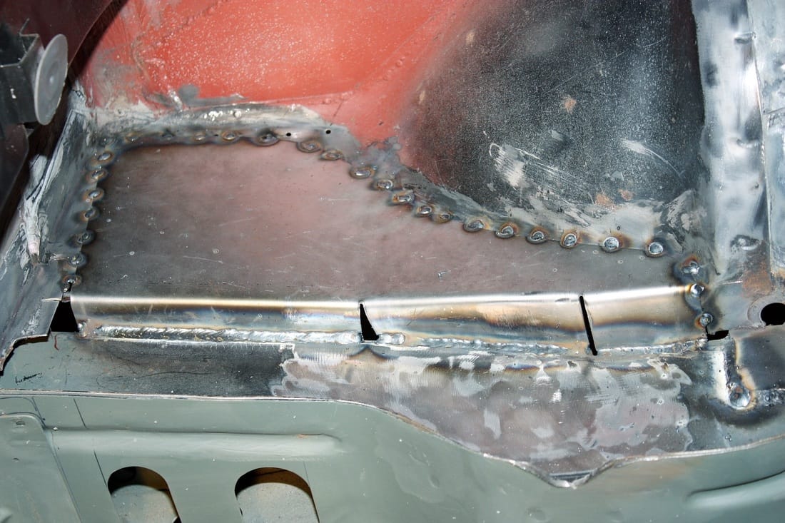
Once I was happy with the fit, I measured carefully and cut the opposite ends of the tubes to fit tightly against the 2"x4" frame rail reinforcement. Then I drilled holes in the gusset (red arrow) to rosette weld the longitudinal braces in the same way as I did the transverse brace:
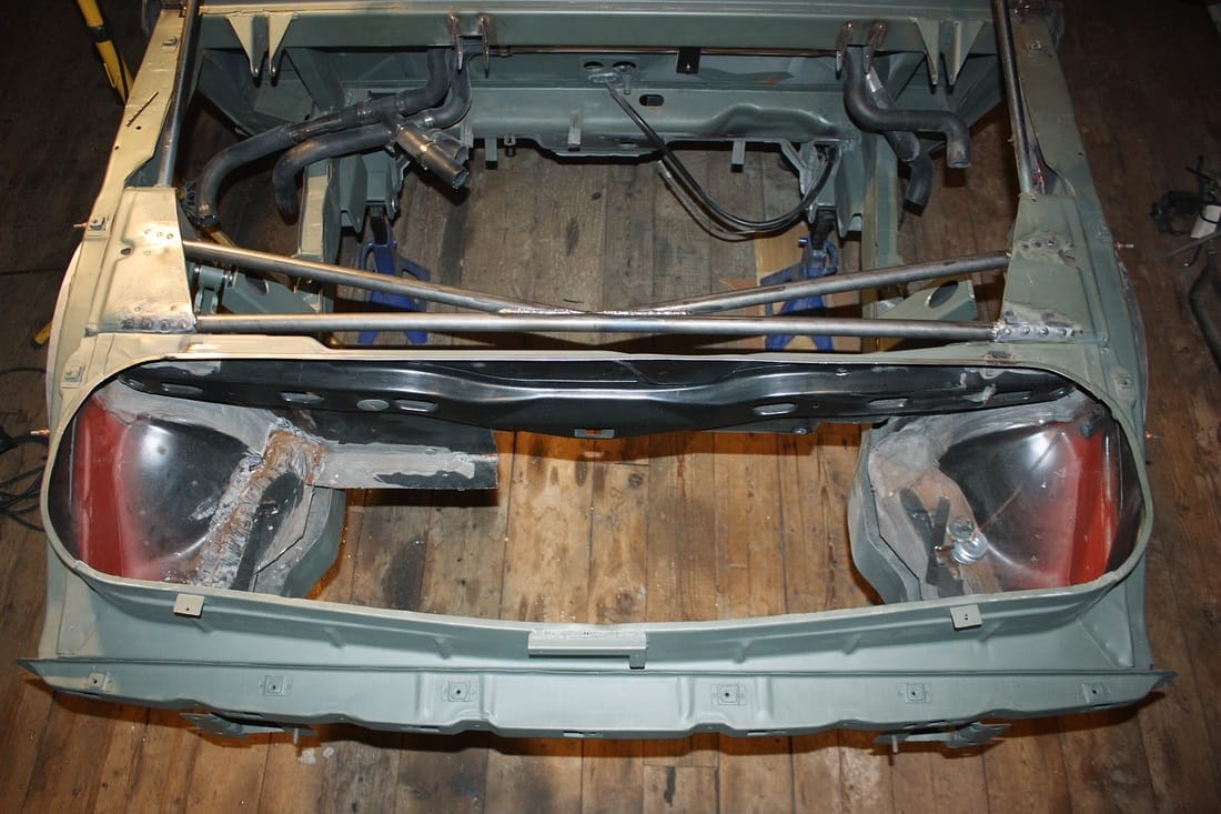
Here's the result:
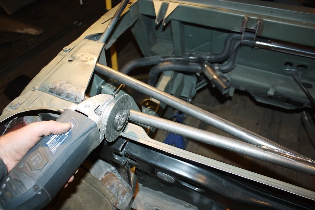
With those new braces in place, the stock Fiero strut brace was redundant. The cut-off wheel made short work of the centre section and what remained of the forward trunk wall:
Ta-dah!
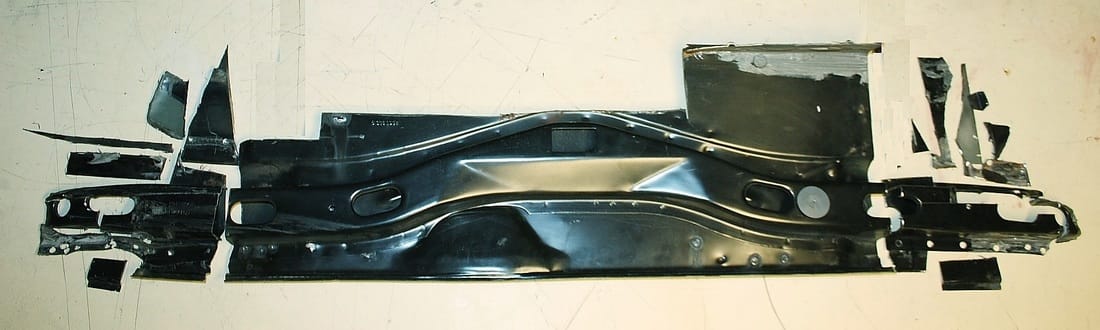
I still had to deal with the ends of the old strut brace by first scraping off the factory seam sealer and drilling out the spot welds:
They resisted my efforts nonetheless since the spot welds along the lower edges were hidden. The car had obviously been put together in a different order than I was taking it apart! It was a good thing I didn't need to save these pieces since nothing resists the angle grinder. Total weight of the OEM strut brace and upper front trunk wall: 6.25 kg (13.8 lbs):
I was finally ready to work on the vertical braces:
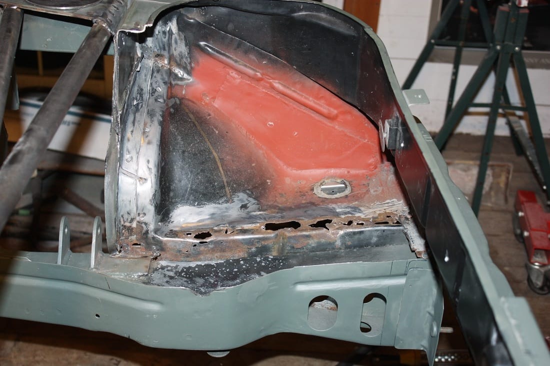
... or so I thought. I got a nasty surprise when I removed the remnants of the little shelf in the trunk area:
The rust-bug had infiltrated both sides of the trunk shelf and was threatening to creep down to the lower frame rail:
I cut out the affected areas on both sides and replaced the sheet metal. Then I ground the paint and the galvanized surface off the top of the lower frame rails:
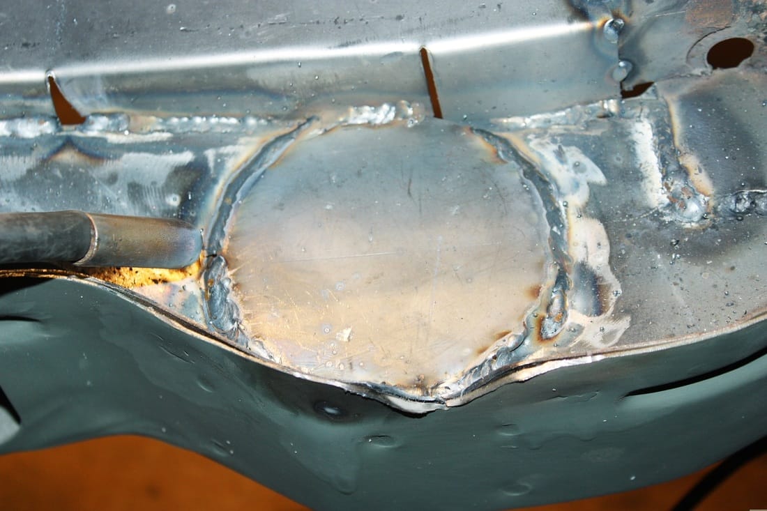
Next, I cut a pair of 0.125" thick circular frame reinforcements to weld to the frame rail:
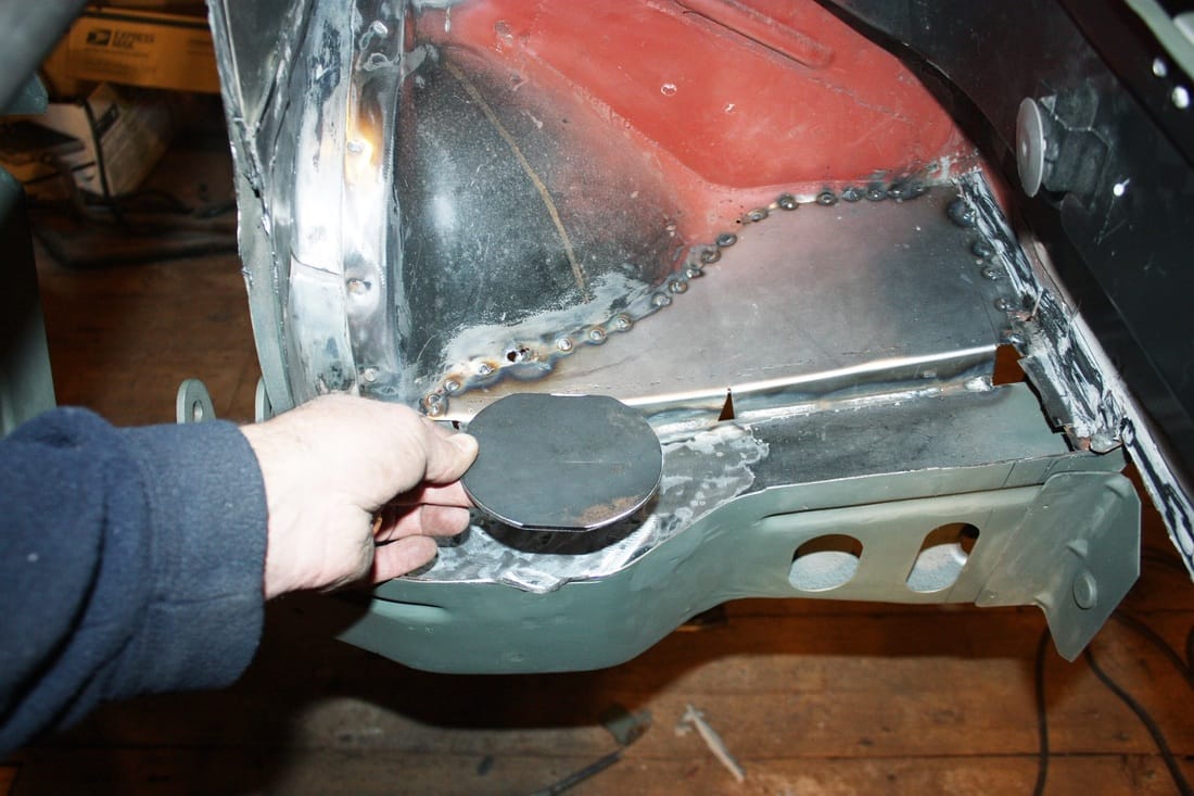
Once they were welded in place, they formed the base of the vertical braces to help spread the loads:
Making the vertical braces was next. The lower ends (where they would be welded to the new circular reinforcements) were simple angle cuts on the ends of the tubes:
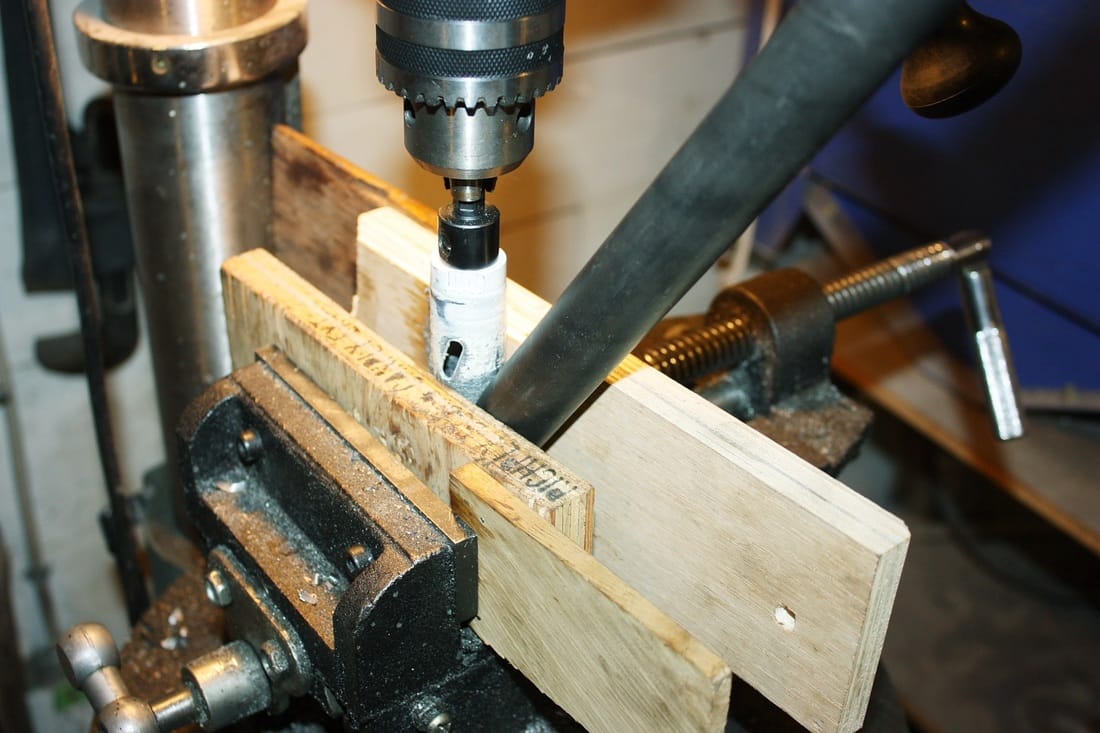
The upper ends were more complicated. Unlike the longitudinal braces, at least the vertical braces could be clamped into the drill press without interference. But the vertical braces are not only angled downward, but also rearward, creating a compound angle. I used up more than one spare piece of sacrificial electrical conduit before I got the right combination of wooden wedges on the drill press:
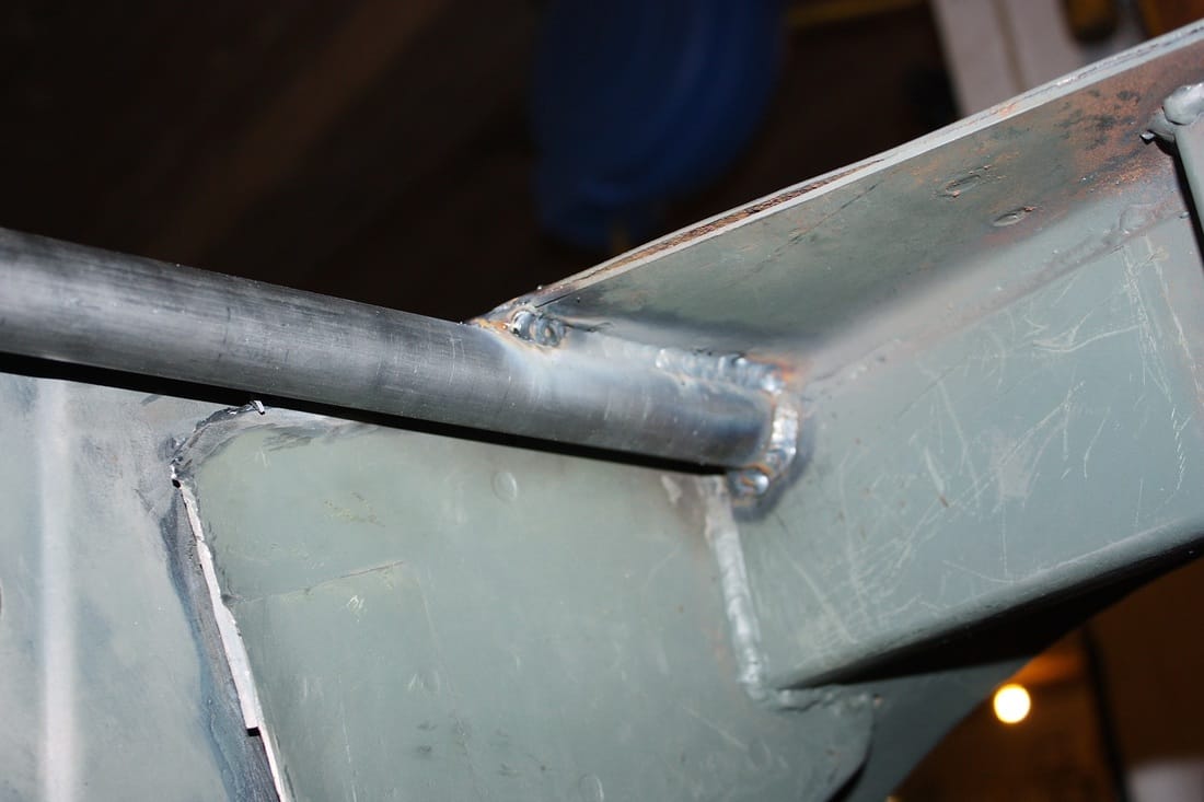
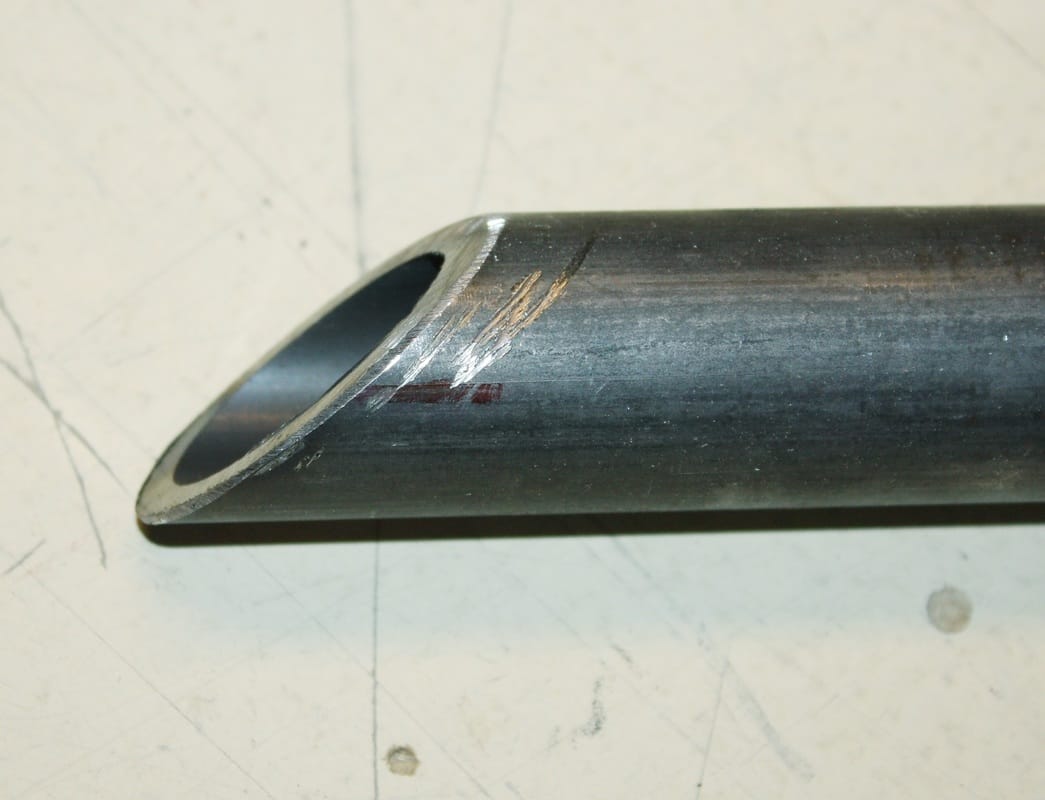
Here's the resulting end-cut:
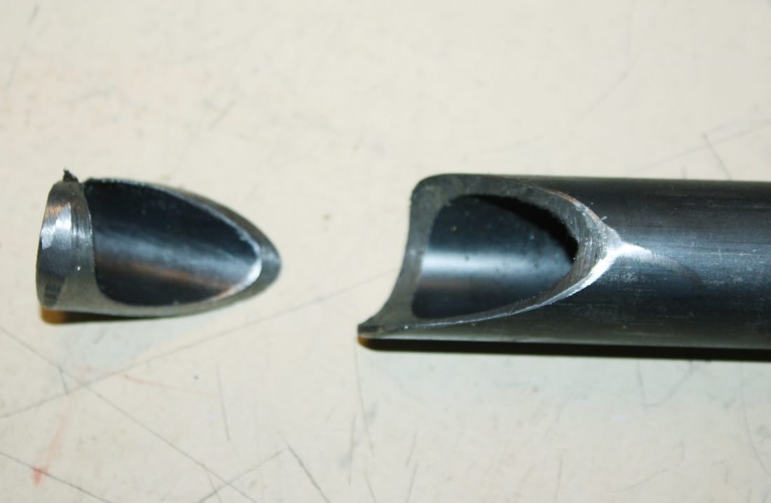
And here's a close up of how well they fit up against the transverse brace:
Once the top ends were tacked in place, I welded the bottom ends of both vertical braces to the circular reinforcements on the lower frame rail:
And with one last pass of the MIG at the upper end, the new cross-car brace was complete!
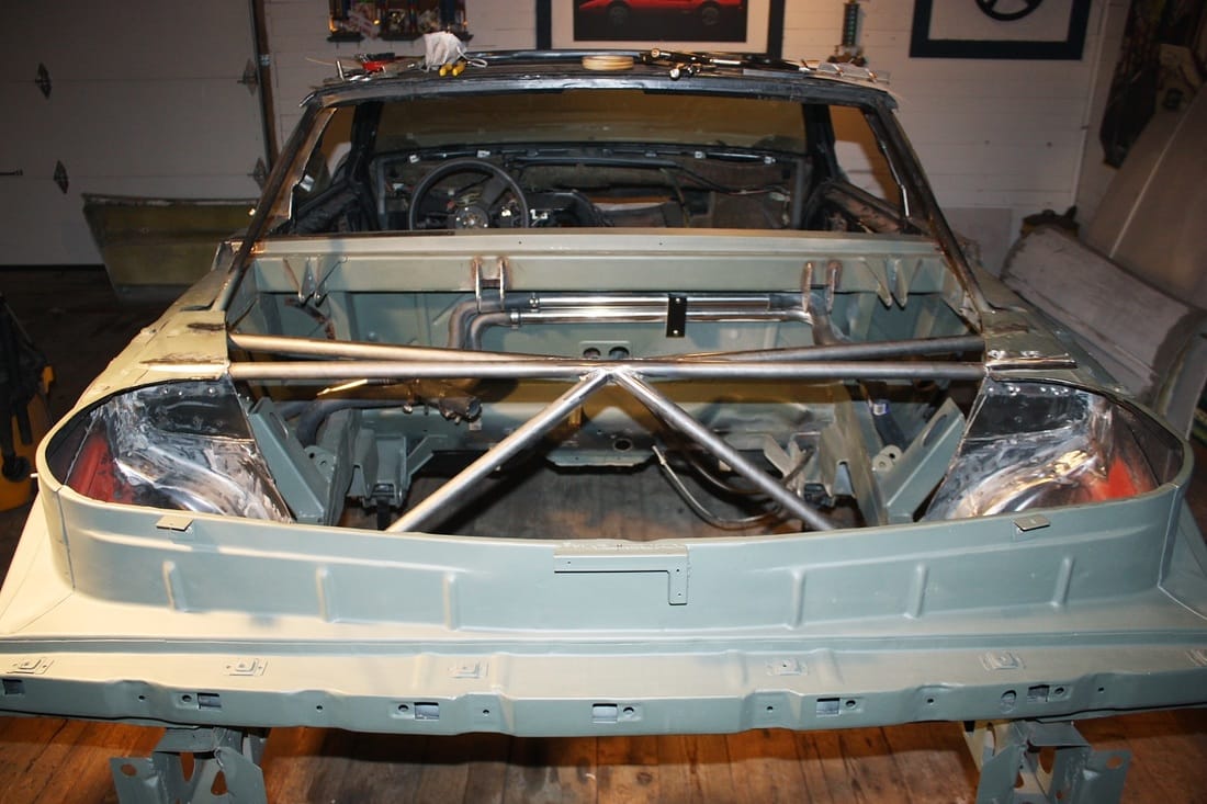
Total weight of the new brace: 7.64 kg (16.8 lbs). That works out to 1.4 kg (3.0 lb) net increase in weight... not bad for what surely must be increased stiffness and much better aesthetics.
Next up: The B-pillar.

 RSS Feed
