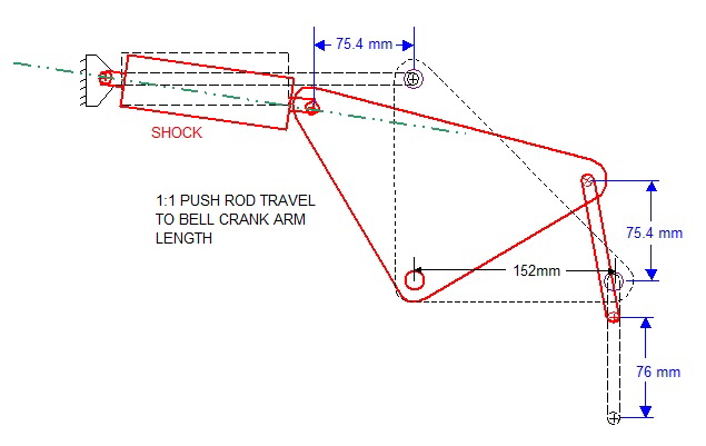
At the end of Post #40 I stopped short at fabricating the new upper suspension mounts since the outboard mounts needed to serve double duty as pushrod mounts as well. With the details of the pushrod sorted out, I could delve back into the metal work.
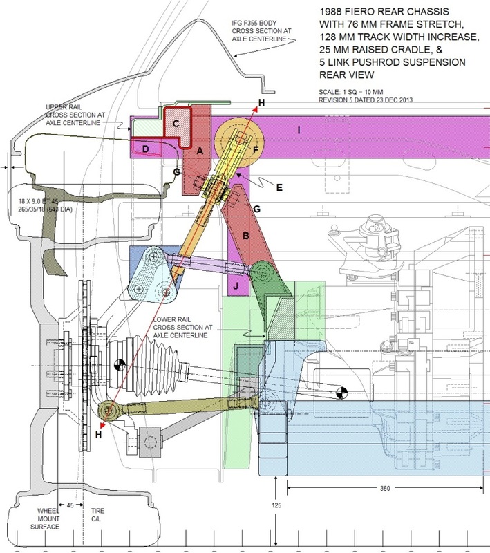
The new upper links are attached to the top of the knuckle in-line with the old upper strut mounting hole using a pair of custom brackets. The aft bracket is just a flat plate of steel and is really only necessary to locate the lower end of the shock pushrod. The forward bracket is more complicated since it serves to locate the lower end of the shock pushrod and provide the correct angle for the upper trailing link.
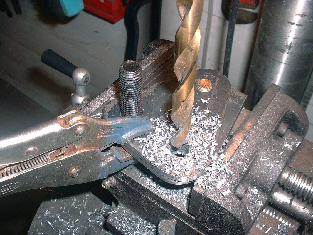
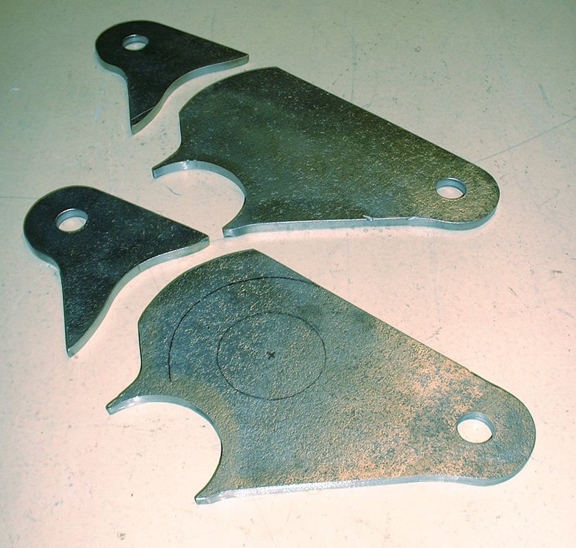
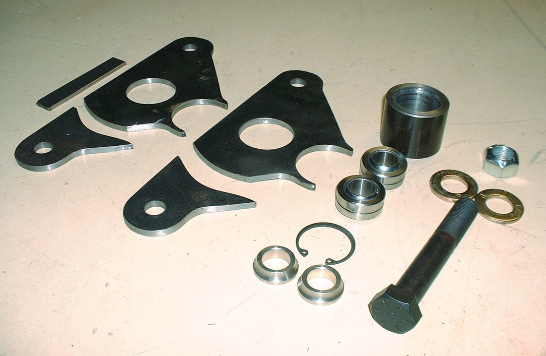
I began by cutting the upper link mounts out of 1/4" steel plate and shaping them to appear more-or-less "factory":
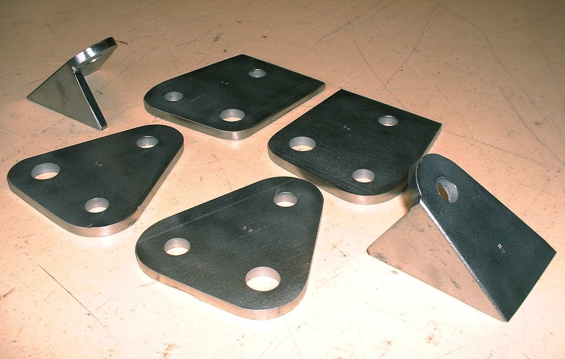
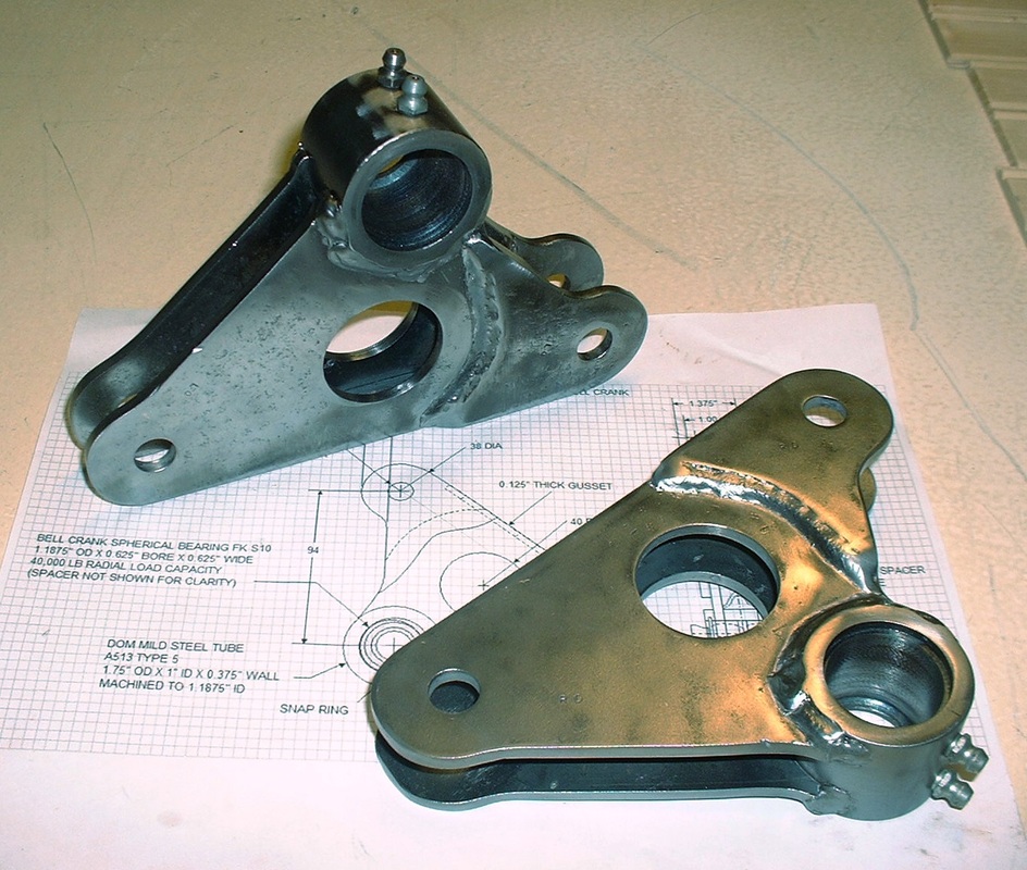
Once again I used my more detailed drawings to create the templates for all of these pieces at the top of the knuckle. The angled piece was carved out from 2" x 2" x 1/4" steel angle iron rather than two pieces welded or one piece bent since the angle iron is stronger than either alternative. Here are all the pieces:
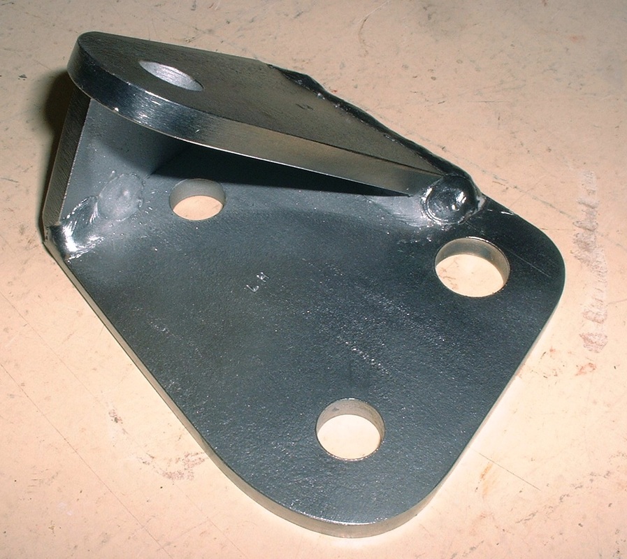
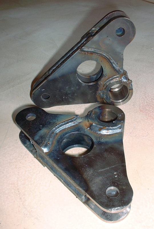
After I bevelled the edges of the parts that make up the forward upper link mount, they were ready for welding. This being a major structural part, I counted on my local professional shop to handle the welding. They welded along the outside edges and wrapped the welds around a half inch or so to the inside edges for additional strength.
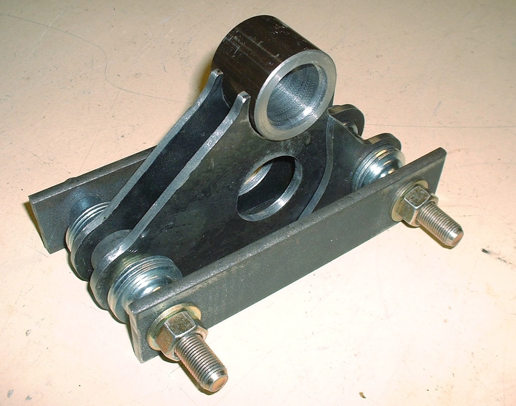
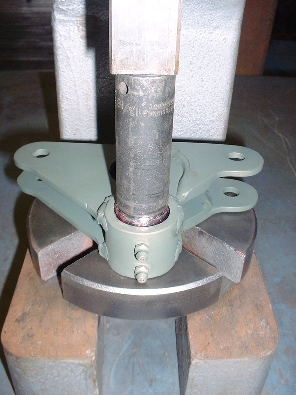
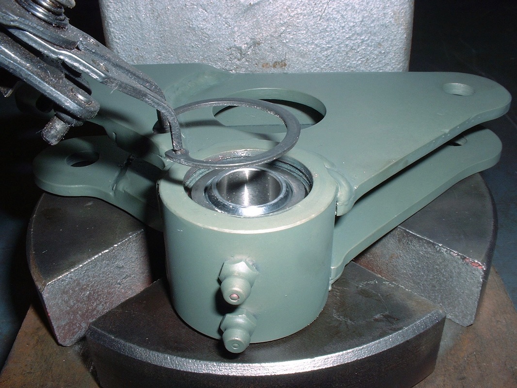
With both pairs of upper link mounts completed, I finally had a chance to mock up the links and the shock pushrod to the knuckle and check for clearances. I used the following parts for the various links:
Upper aft links and pushrods: AFCO 5" X 5/8" swaged tube (P/N 36175);
Upper forward links: AFCO 7" X 5/8" swaged tubes (P/N 36177)
Rod ends (LH thread): QA1 3 piece PTFE lined 5/8"-18 male with 1/2" head bore, 31,390 lb load capacity, 10 deg misalign P/N: HML8-10T
Rod ends (RH thread): QA1 3 piece PTFE lined 5/8"-18 male with 1/2" head bore, 31,390 lb load capacity, 10 deg misalign P/N: HMR8-10T
Jam nuts RH thread (5 per package): QA1 5/8"-18 P/N JNR10S-1-5PK-QA1
Jam nuts LH thread (5 per package): QA1 5/8"-18 P/N JNL10S-1-5PK-QA1
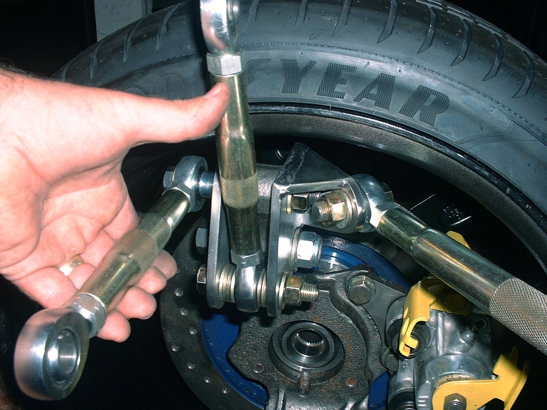
I temporarily used washers as a means to centre the shock pushrod, though I had ordered proper spacers.
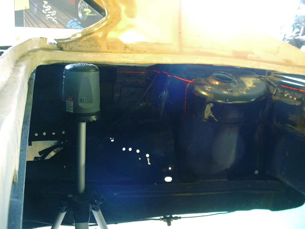
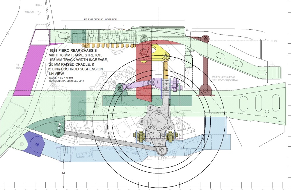
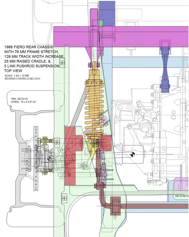
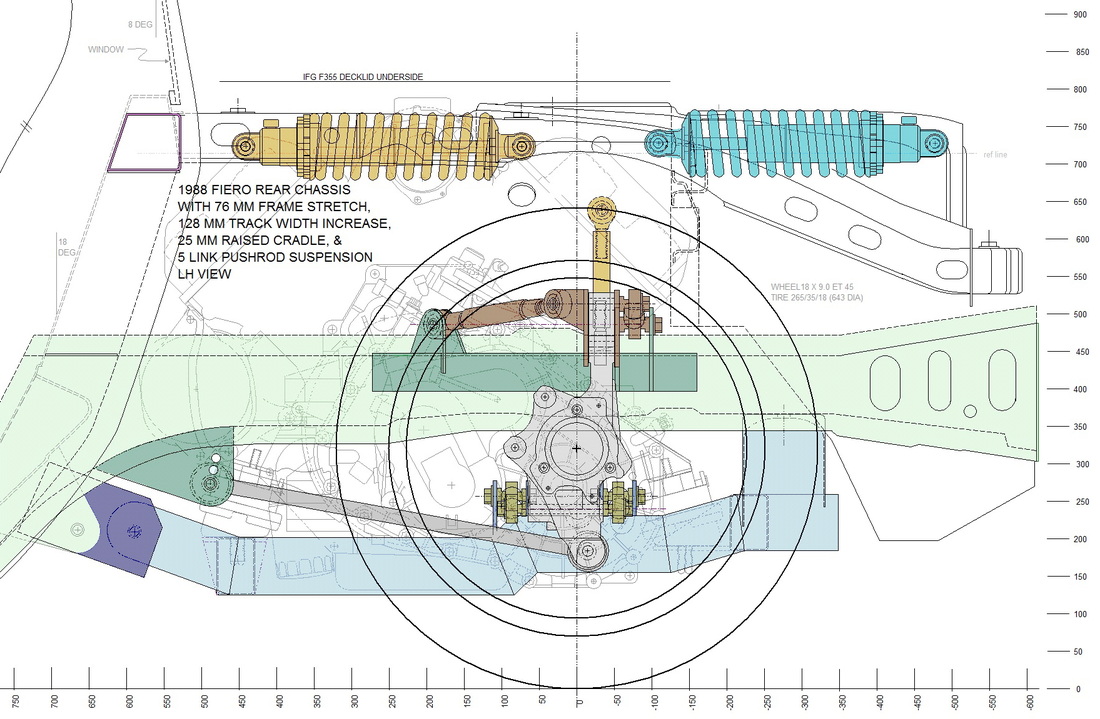
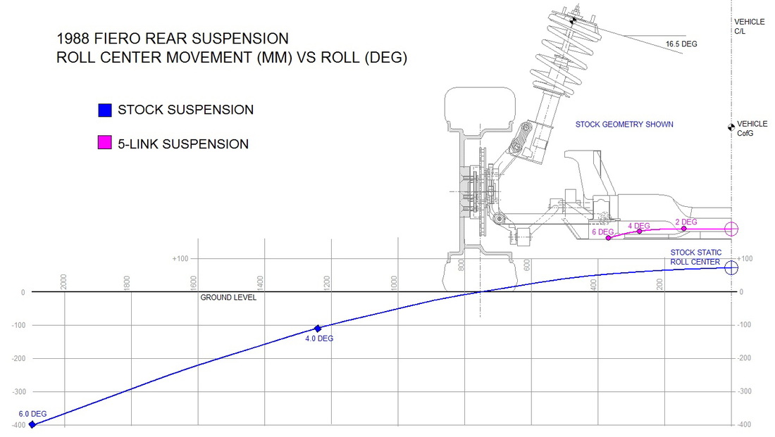
With the outer end of the upper links mounted, I started working on the inner mounts attached to the main frame rail. The first step was to set up my multi-axis laser level and project a vertical cut line onto both strut towers. As shown in the drawing from my last post the stock strut towers were in the way and no longer needed:
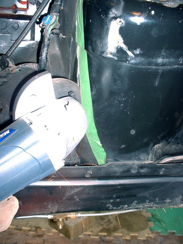
I used an angle grinder with a cut-off wheel to make the cuts:
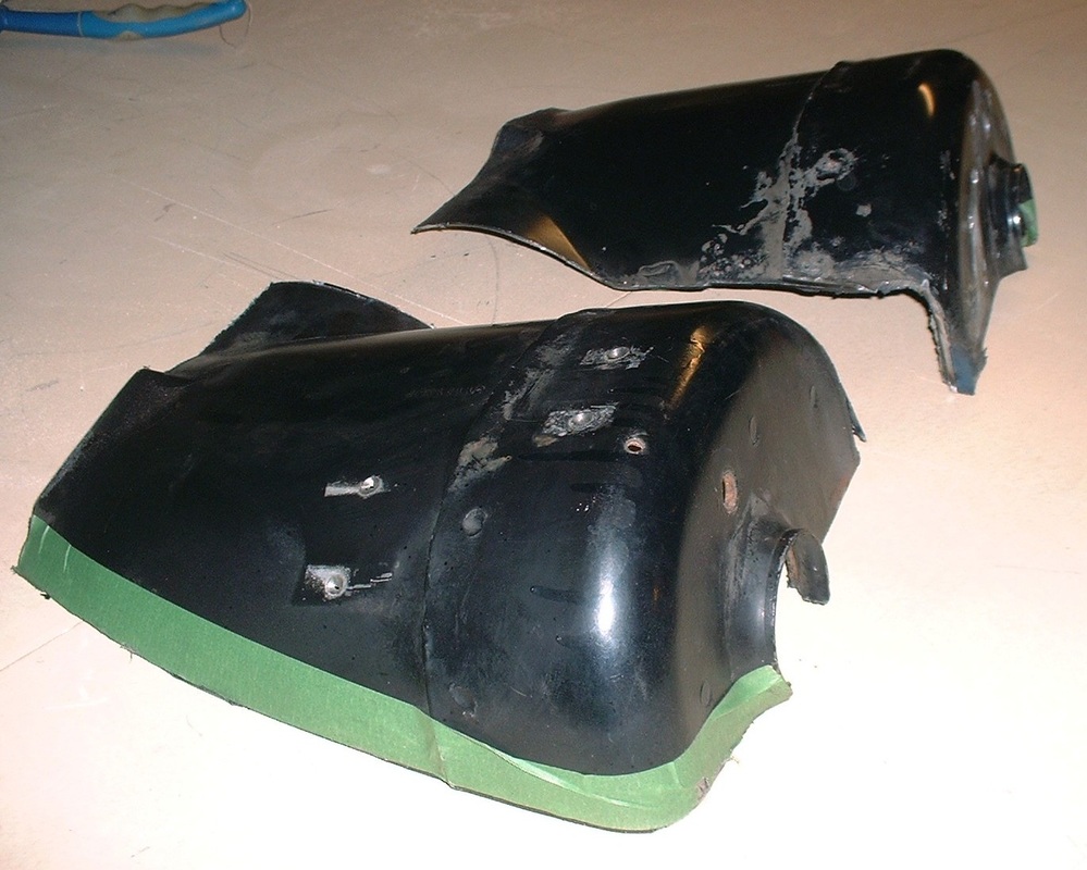
These were the amputated parts:
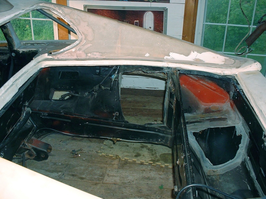
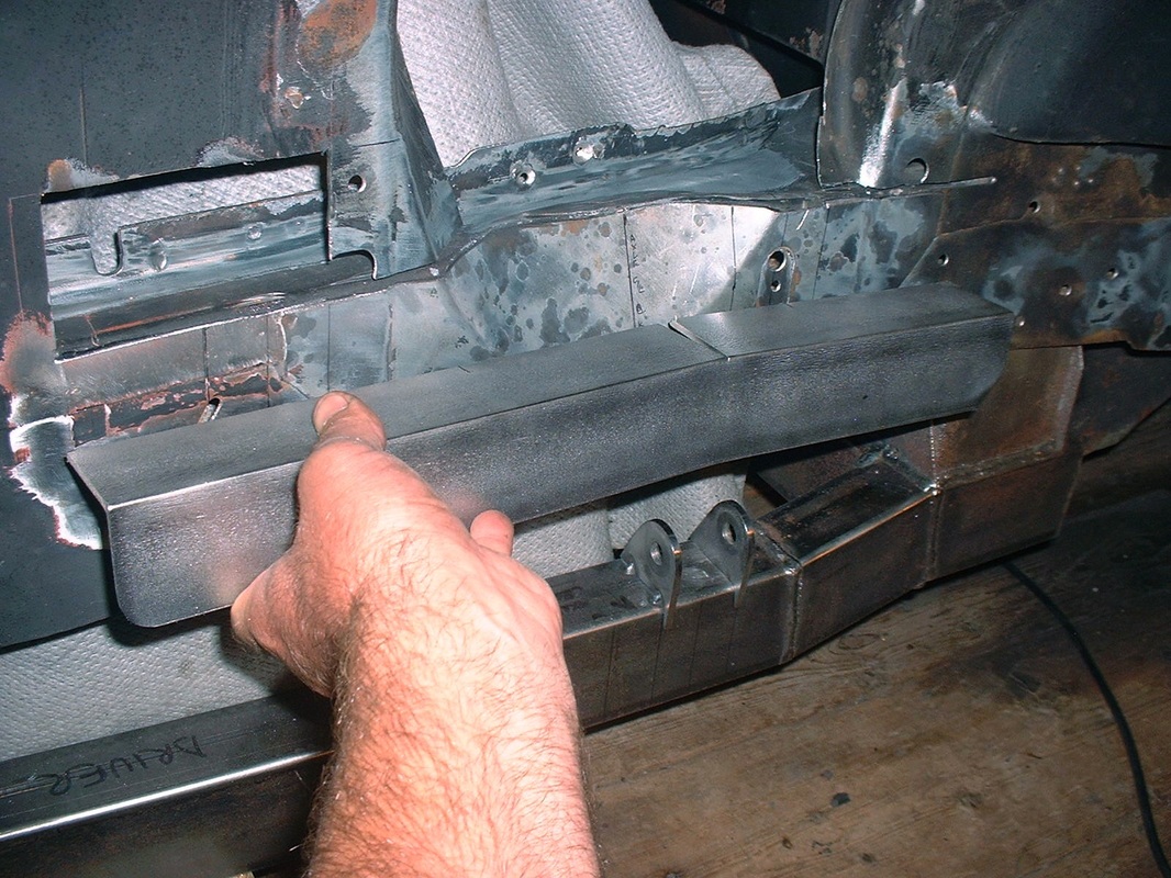
With the towers out of the way I had better access to the lower frame rail. This is the passenger's side:
I then added a piece of 2" x 2" x 1/8" angled steel to the outside top of the lower frame rail along an 18" stretch to anchor the mounting ears for the upper links and give them a larger surface area to spread the loads onto the rail. This is the driver's side.
Here's the frame stiffener mocked up ready for welding:
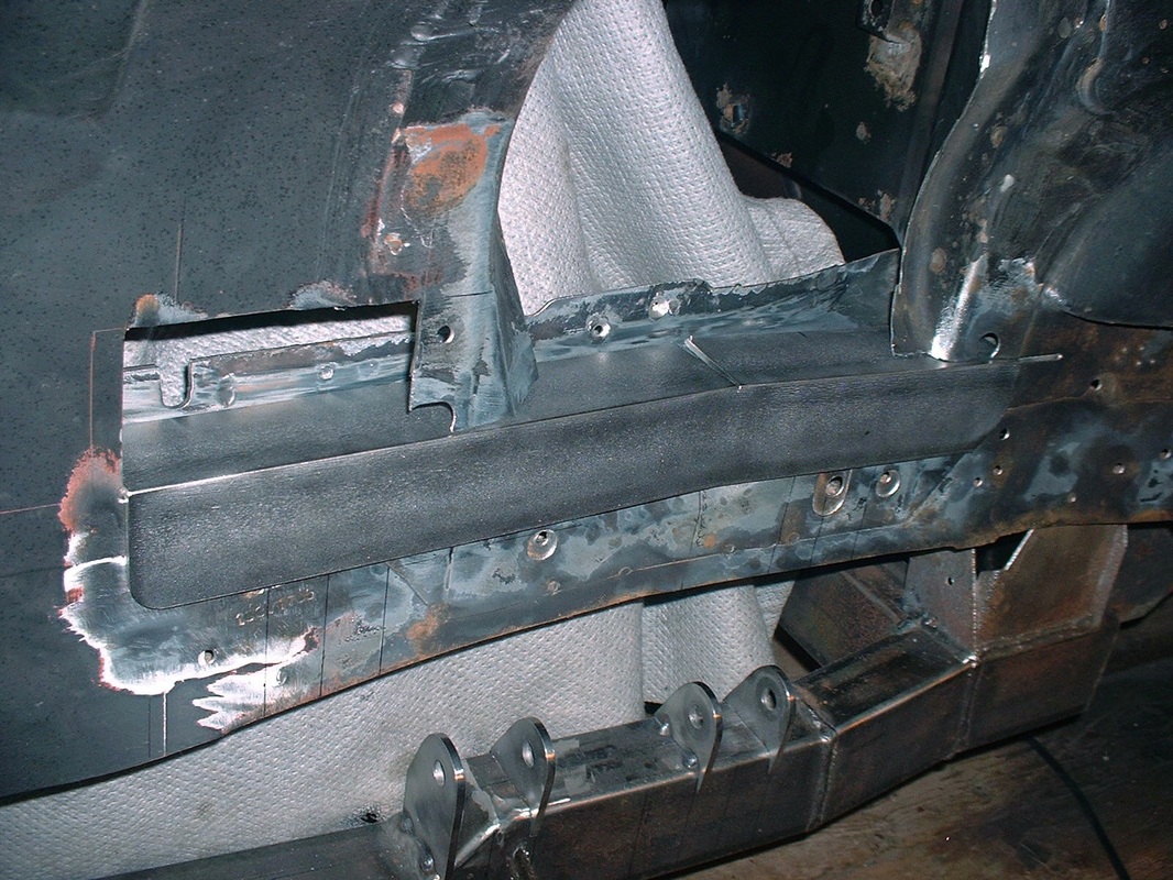
Next I'll fabricate the mounting ears for the upper suspension links and attach them to the stiffener.


 RSS Feed
