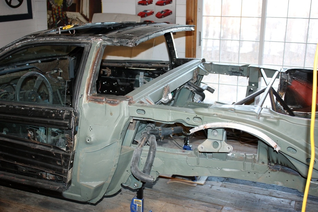
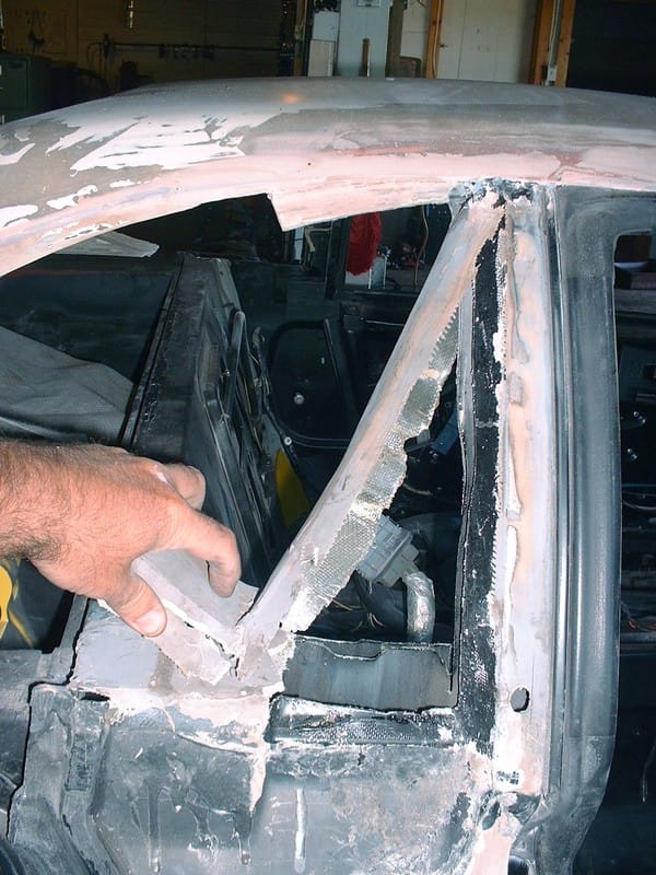
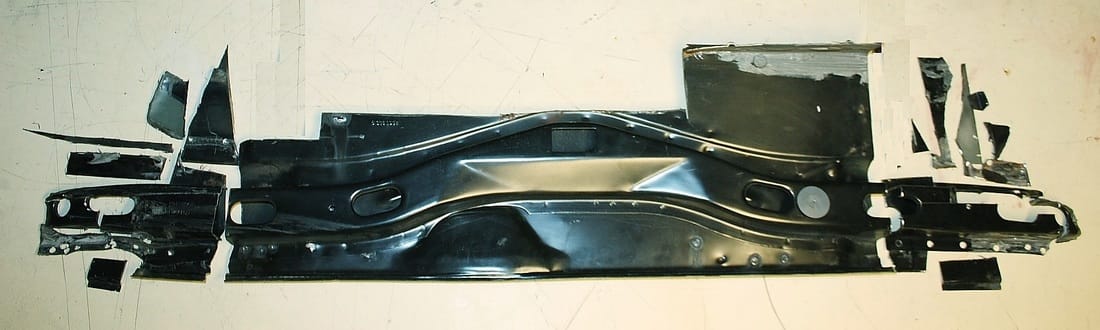
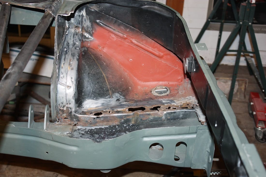
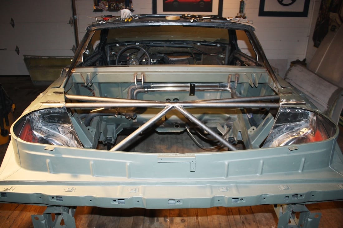
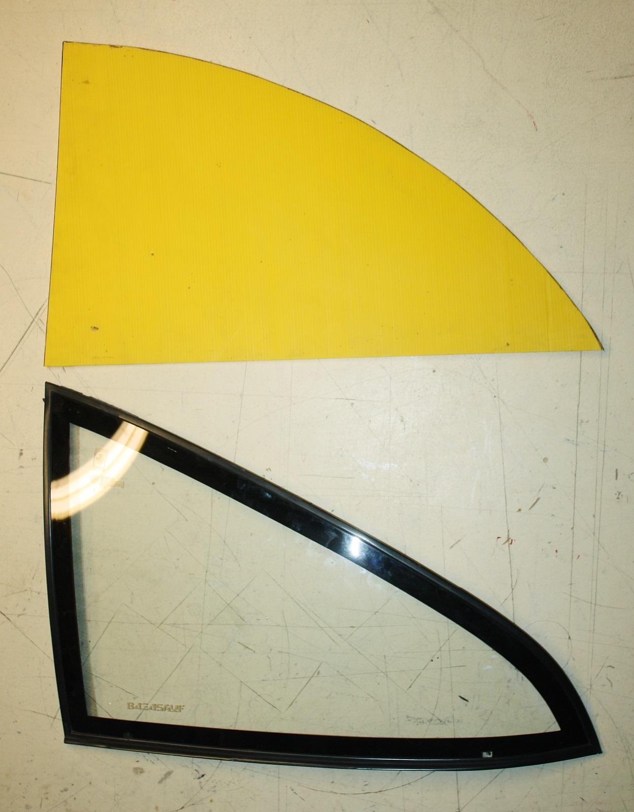
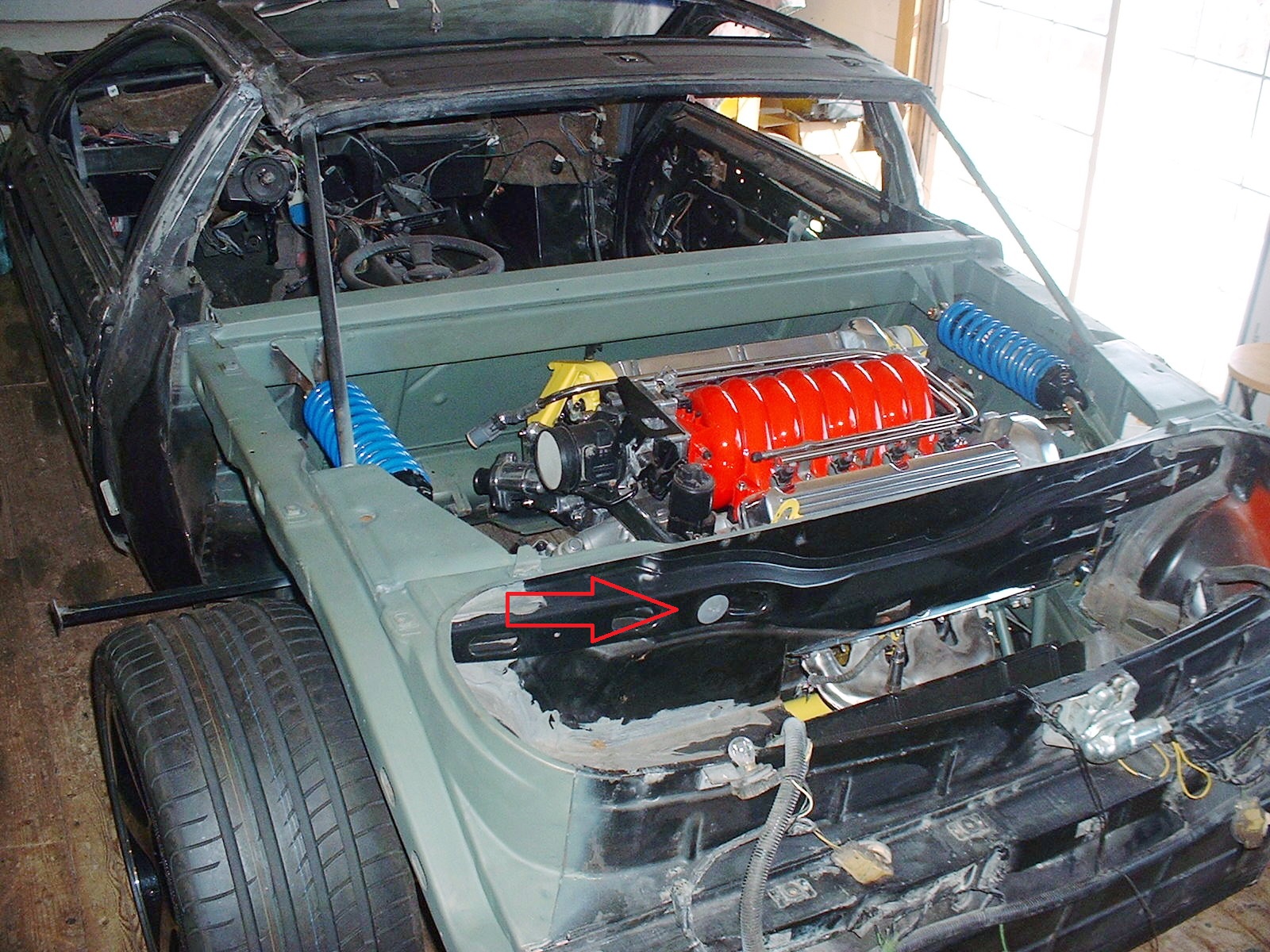
With the old C-pillars out of the way, I decided it would be a good time to work on the lower supporting frame for the Toyota MR2 rear window. Once again, here was the blank canvass from which I was working:
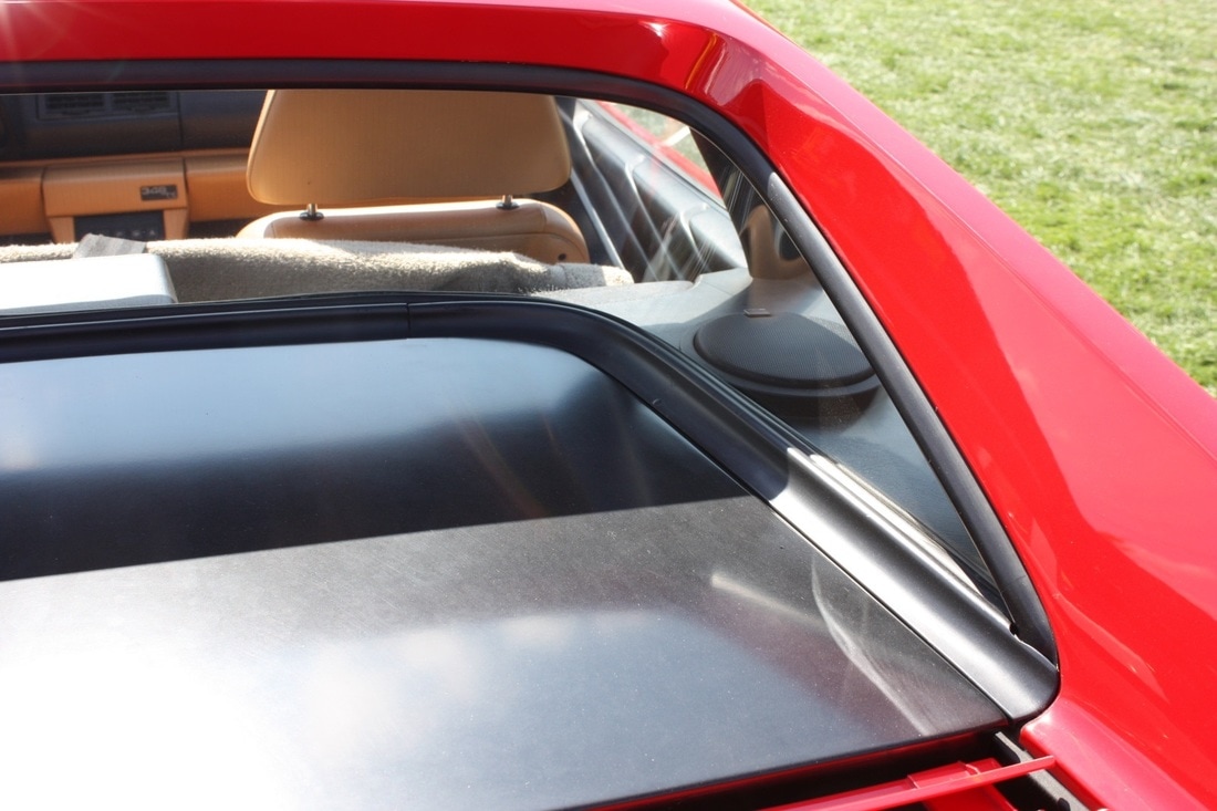
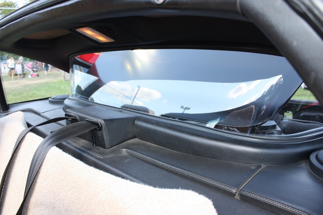
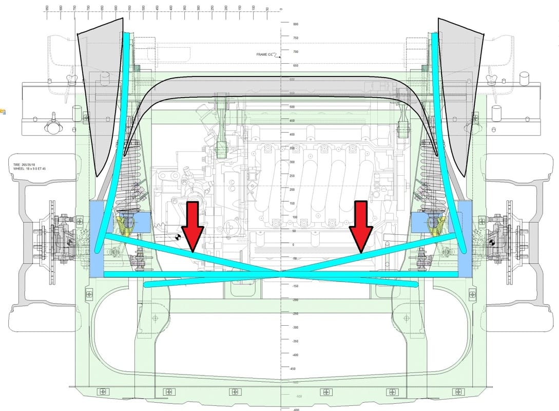
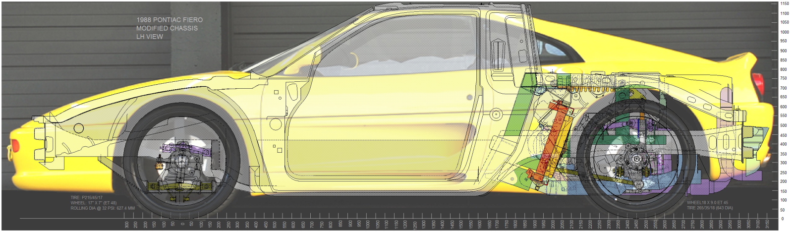
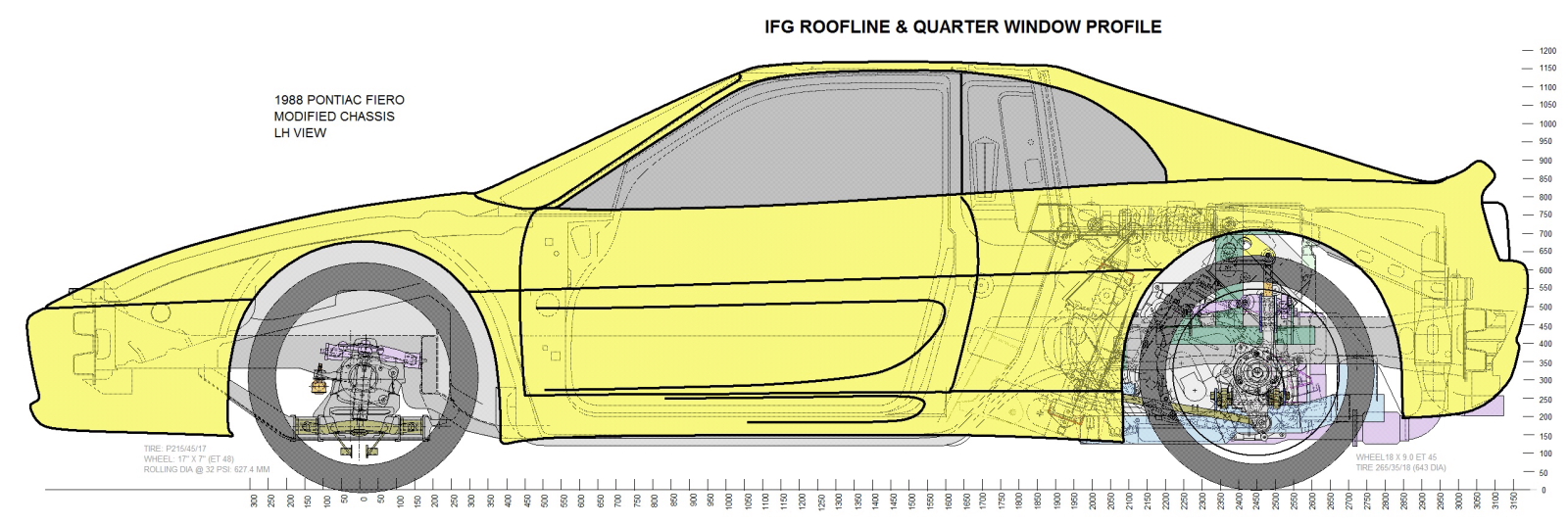
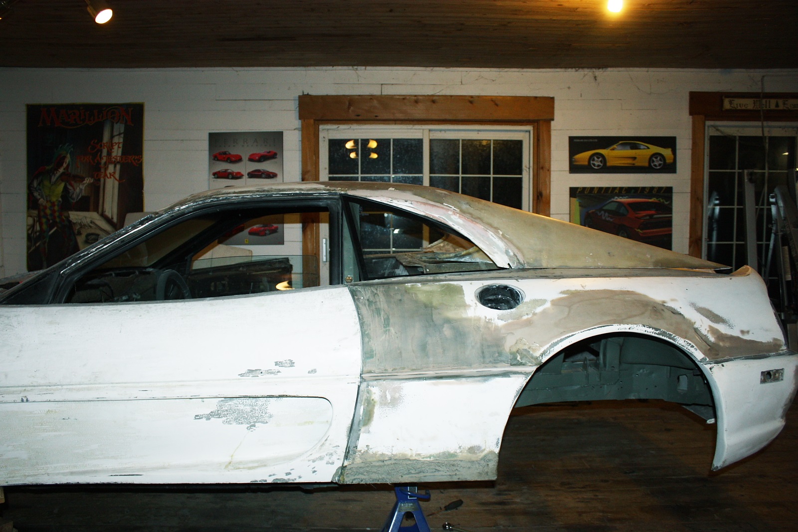
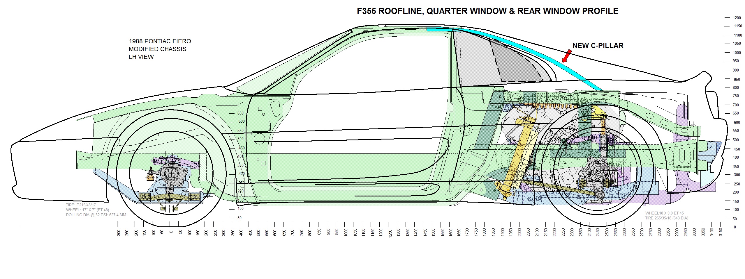
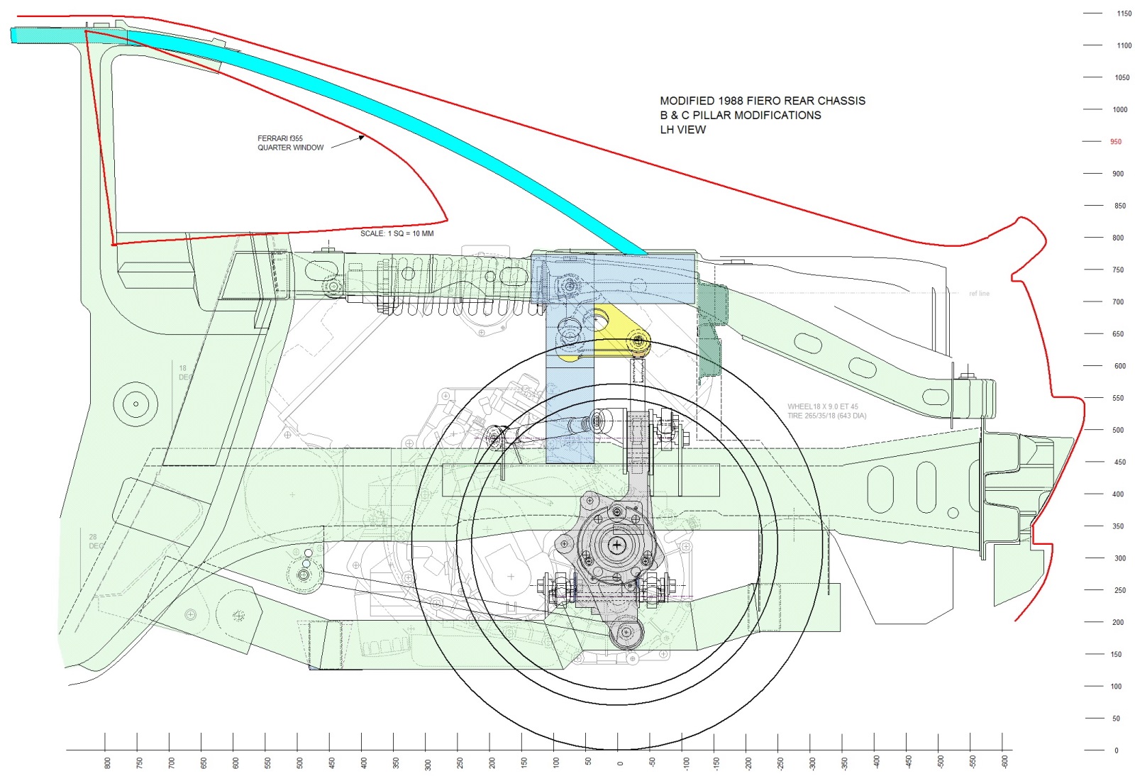
I needed to completely redefine the location of the rear window in 3 dimensions since it wasn't going to sit in the same plane nor height, nor angle as the stock Fiero window. So I temporarily reinstalled the fibreglass rear quarters and the decklid to get a sense for the new height, fore and aft location, and tilt. On the authentic F355, the visible portion of the rear window along the bottom sits about 3/4" higher than the decklid. The gap is bridged with a black rubber quarter-round. This is an F348, but the F355 is identical:
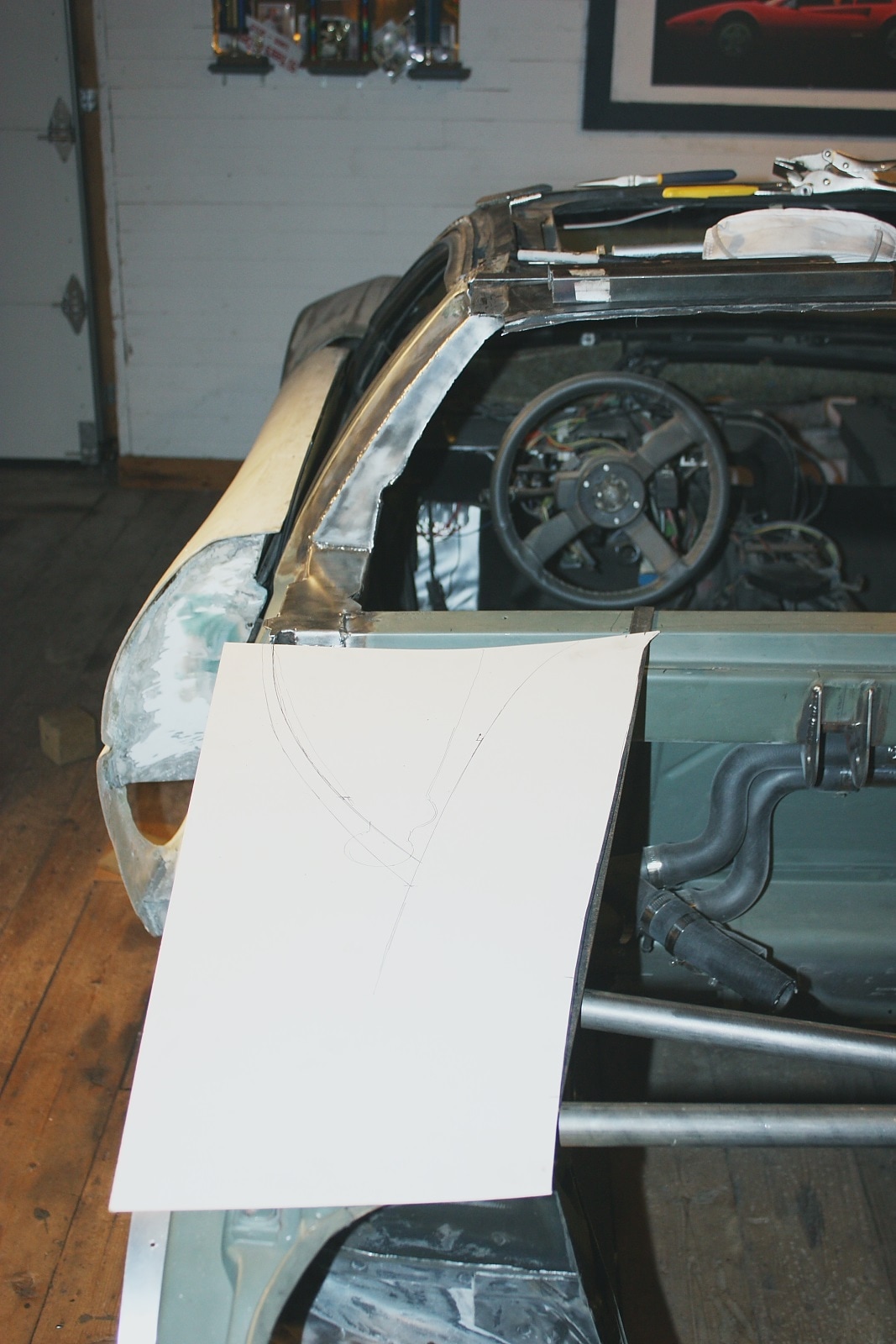
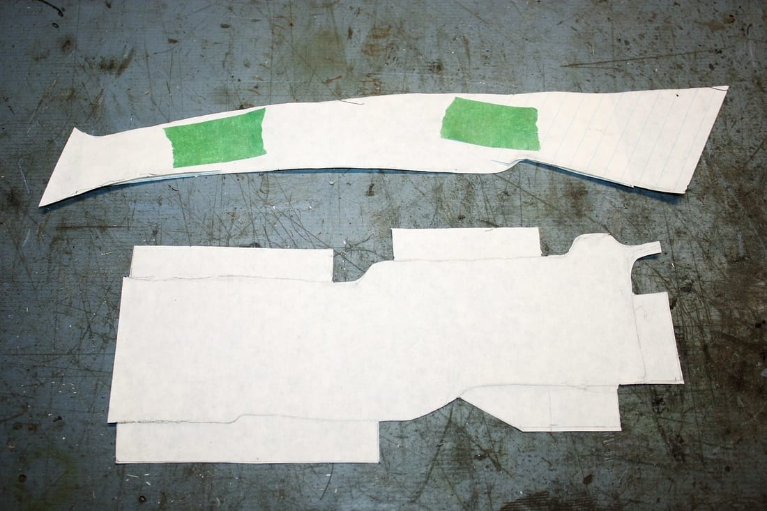
Once I got a feel for the correct height and position, I centred the MR2 glass on the chassis and traced the outline on a large cardboard template. The template allowed me set aside the glass window and design the support structure without risking an accident with the glass:
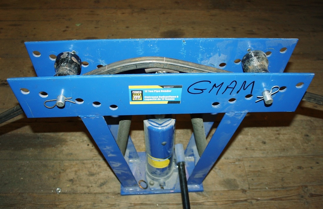
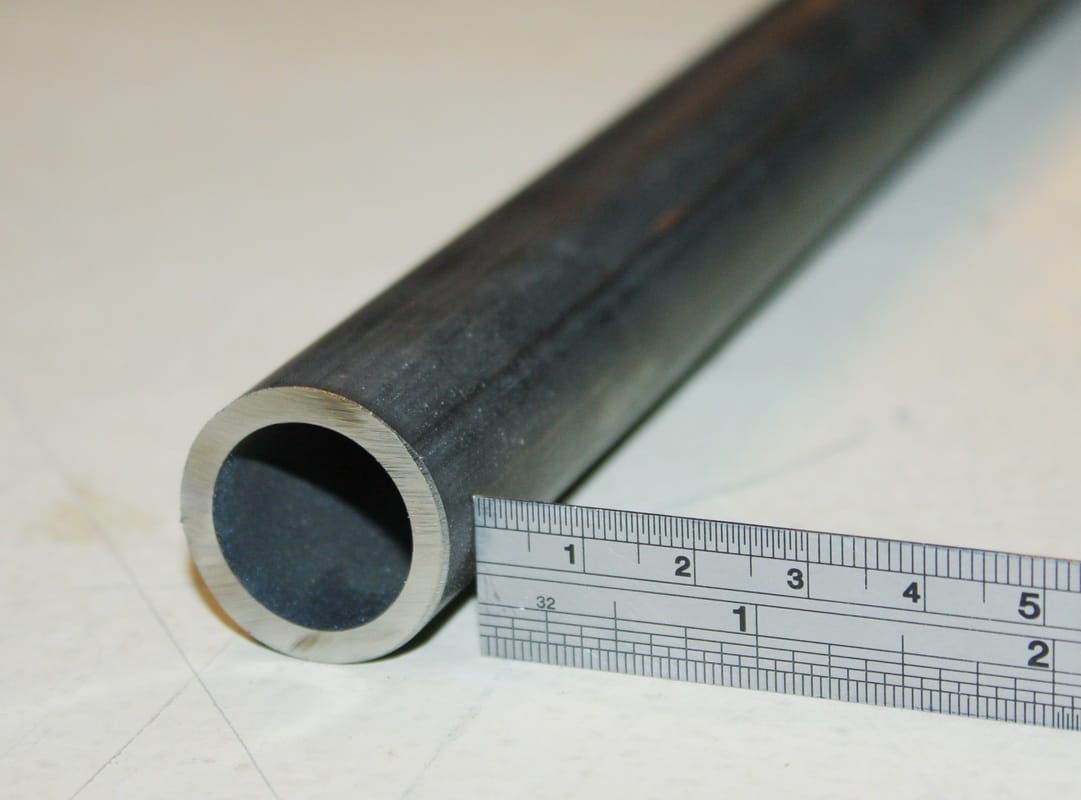
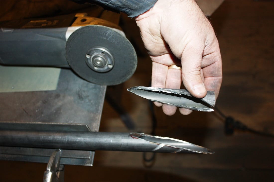
| The new location meant I had to elevate the glass 3/4" higher than the top of the stock Fiero firewall. That made the decision to use some 3/4" square tubing for the base frame an easy choice. It would have to be bent in a couple of relatively tight radii though, so I decided to make a die out of some round stock and an old socket. The die deforms the inside wall of the square tube in a predictable direction (inwards). Without it, the tube would warp as the inside wall tries to shrink with nowhere to go: | 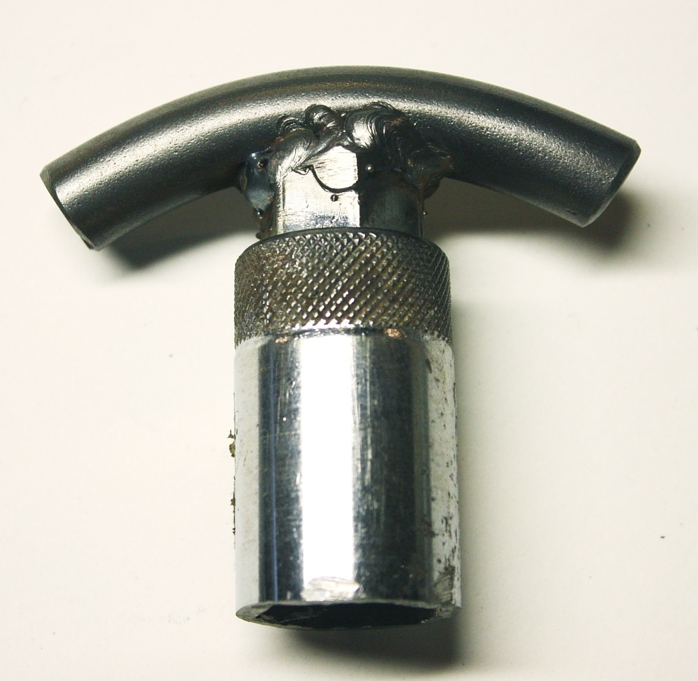 |
I loaded up some tubing into the hydraulic bender and worked my way along the length little by little, checking the profile against the template every couple cycles:
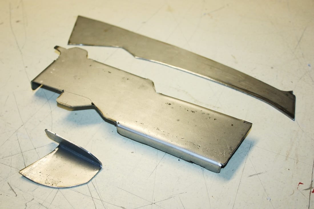
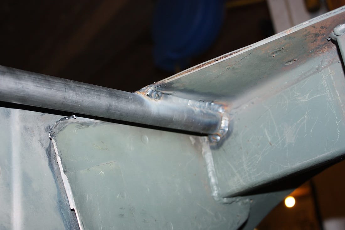
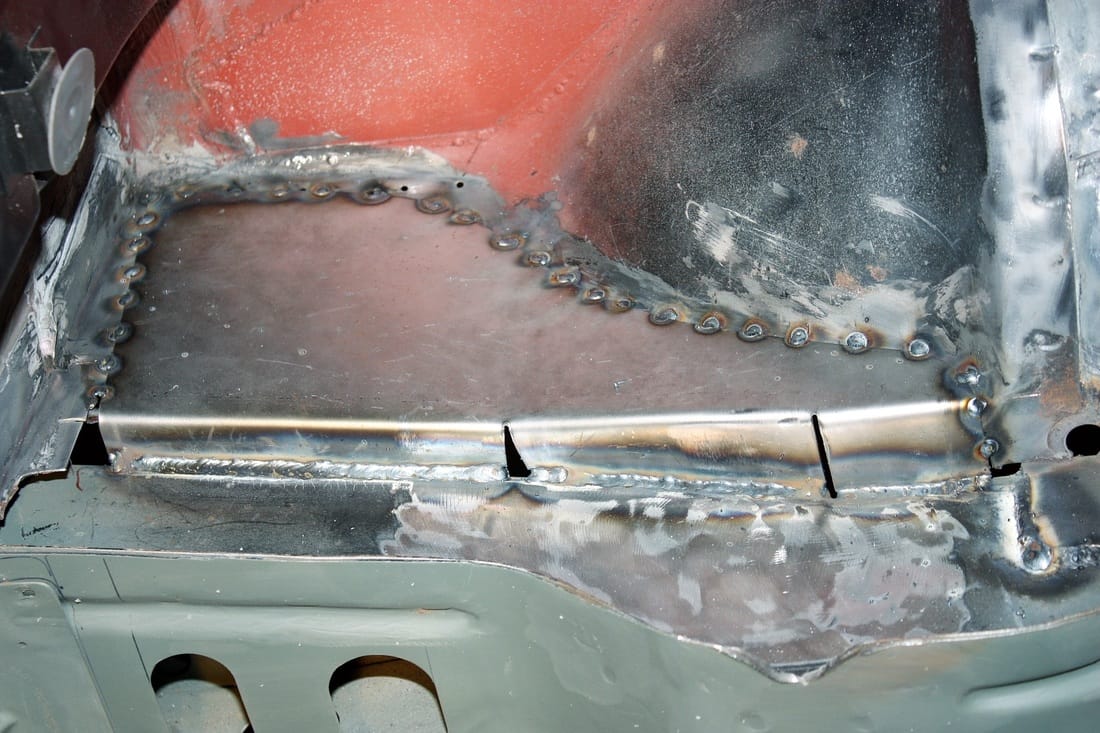
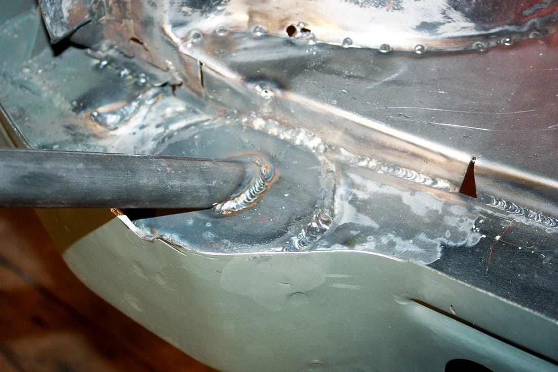
Once it's bent, the square tubing is much harder to straighten out again if you make a mistake, so I formed two halves separately and welded them together. I double checked the curvature with the actual window, and then set about forming a flange to weld to the top of the tube:
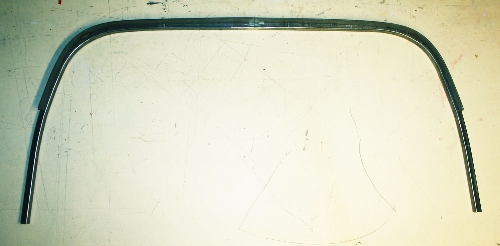
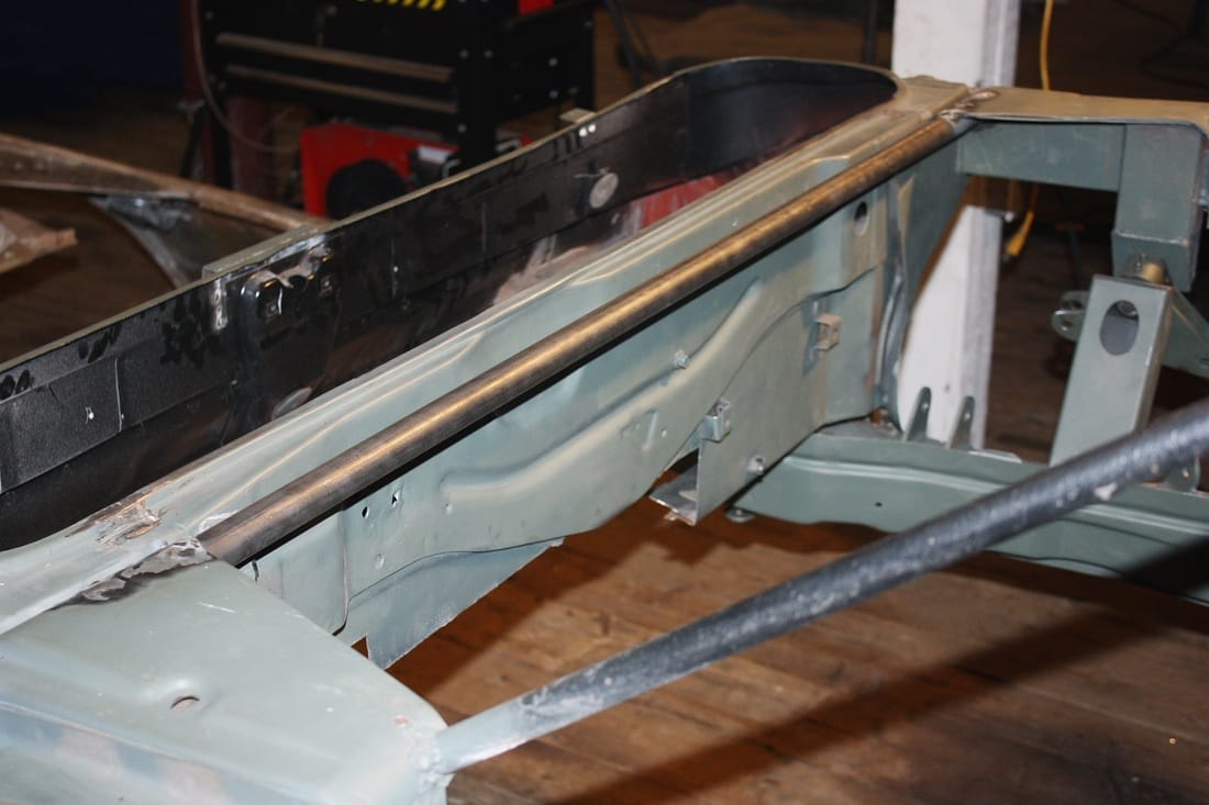
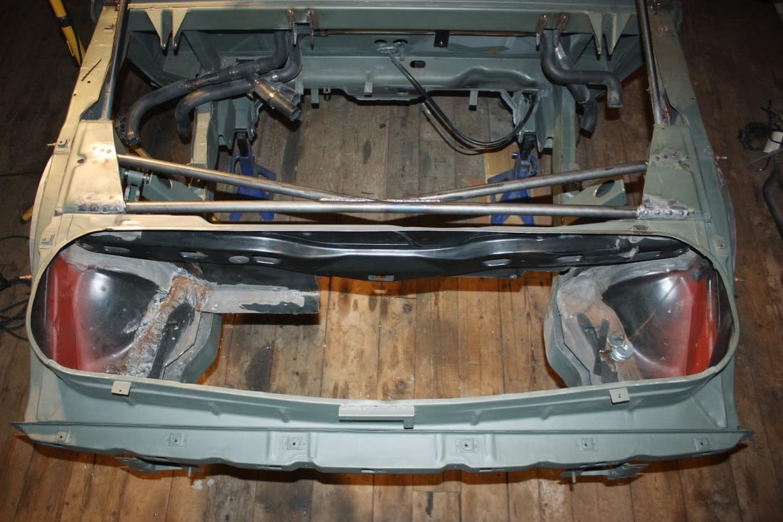
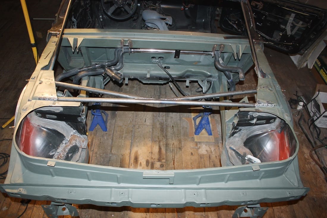
The glass will rest on top of the tube, but the window will be glued to the vertical flange from the outside with urethane adhesive. Here's the lower frame mocked up:
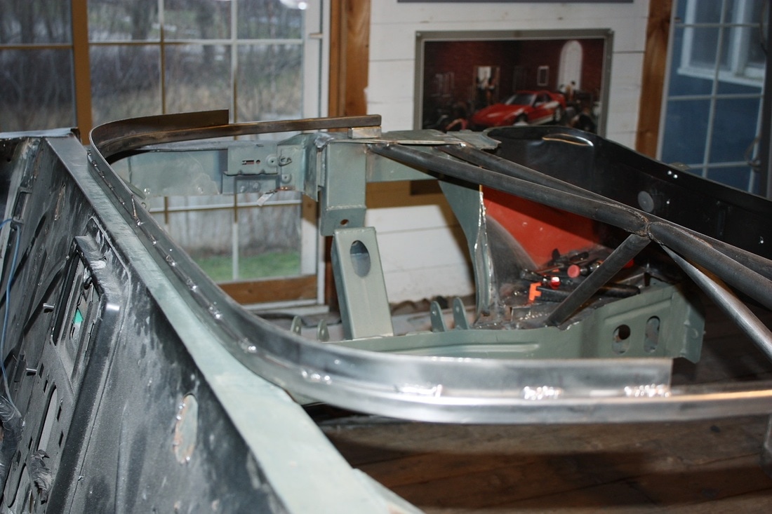
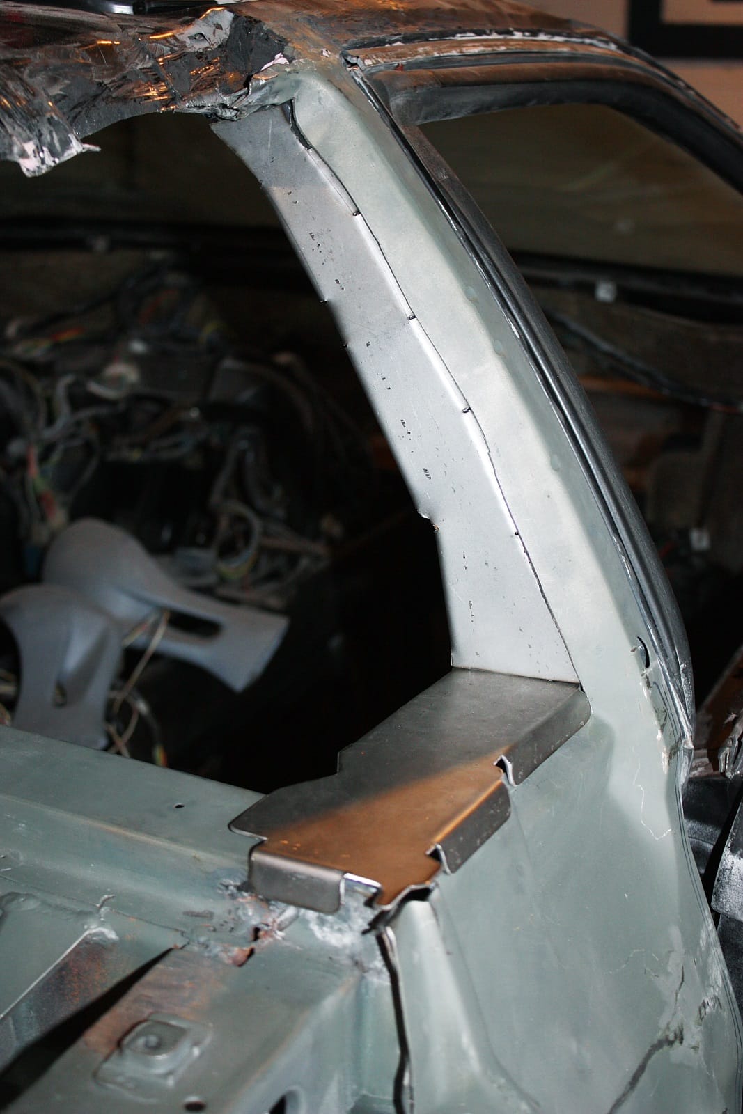
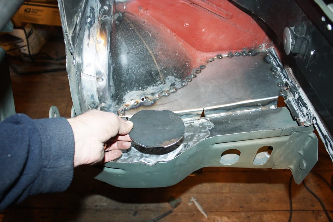
I double checked the fit of the glass onto the flange and adjusted it where necessary. I found that simply welding the flange onto the tube caused the tube to pinch inwards slightly. Note that from the outside, the metal flange will be hidden by the black fader-tape border on the glass and by the black quarter-round trim shown earlier:
This view from inside the cabin shows the fit of the glass against the flange:
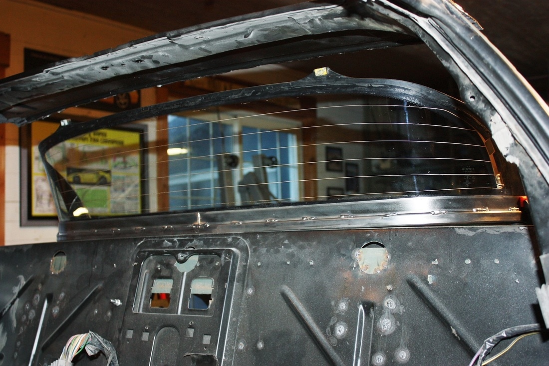
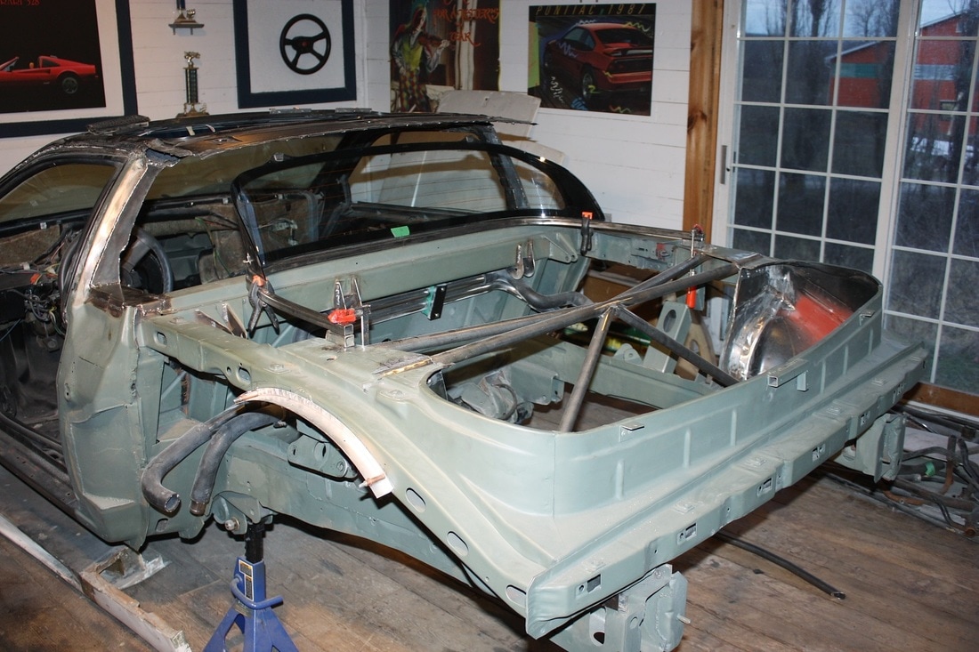
With some upholstery and a little imagination, the rearward view is looking more and more like the real thing:
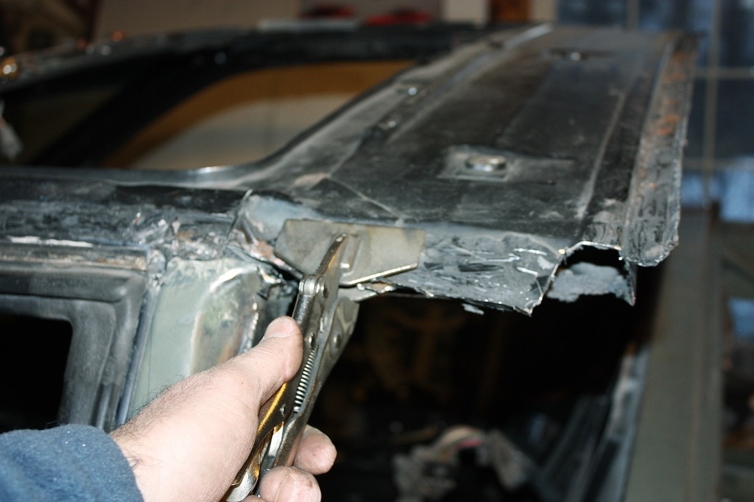
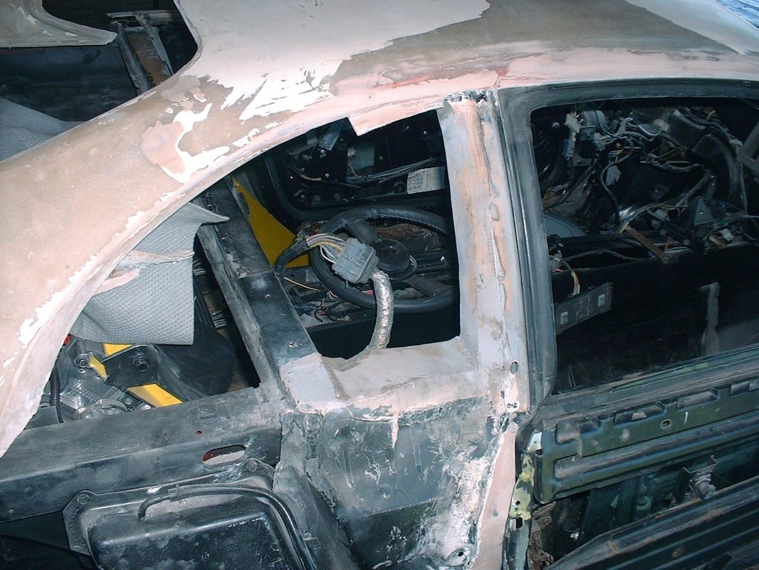
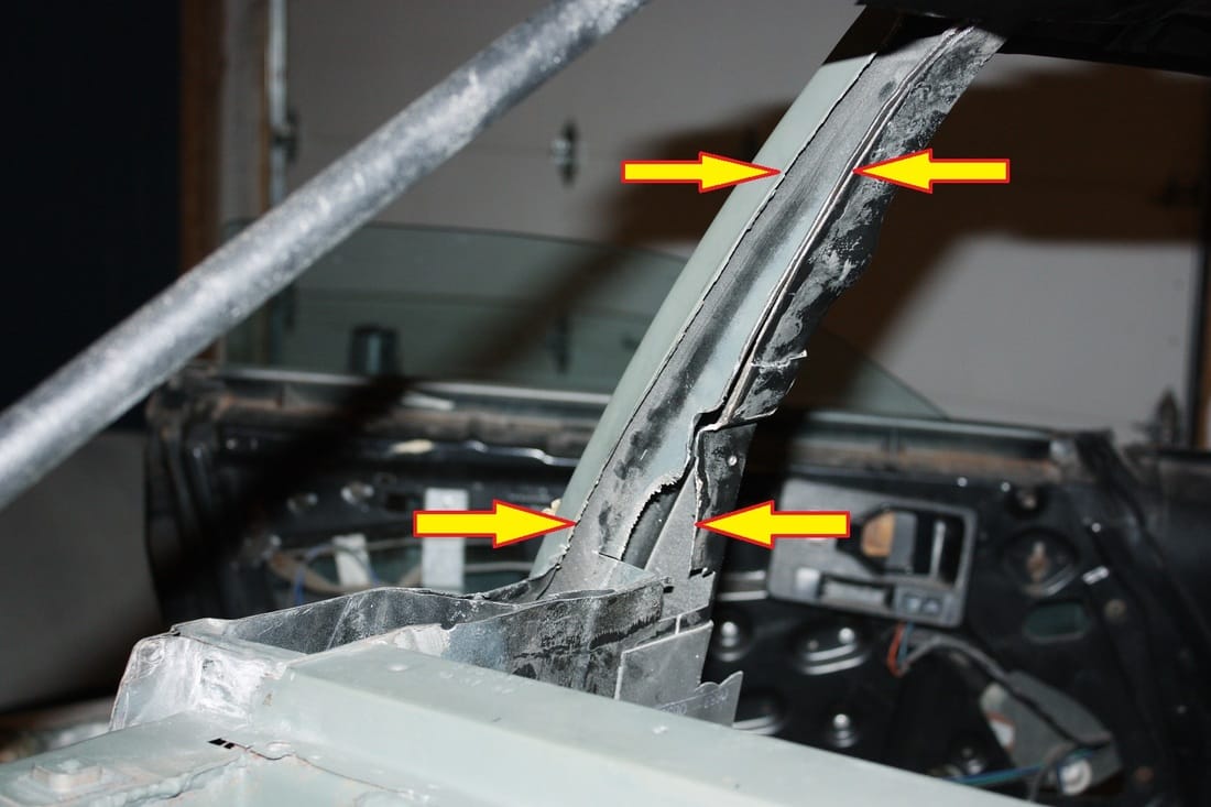
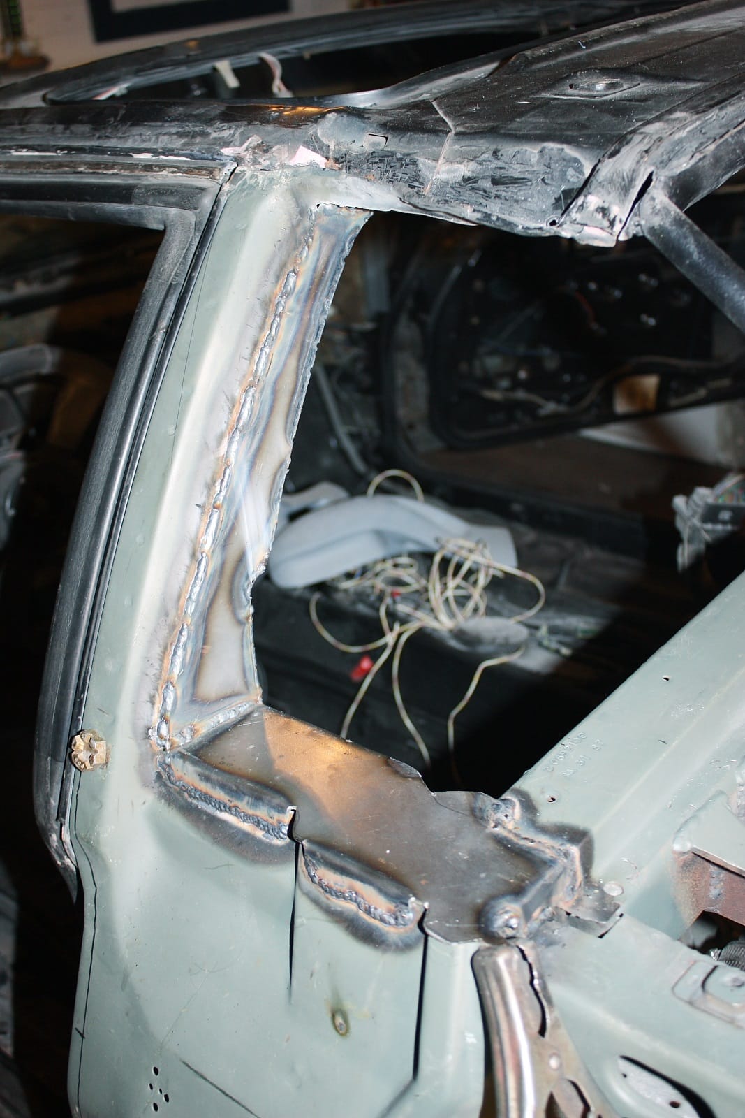
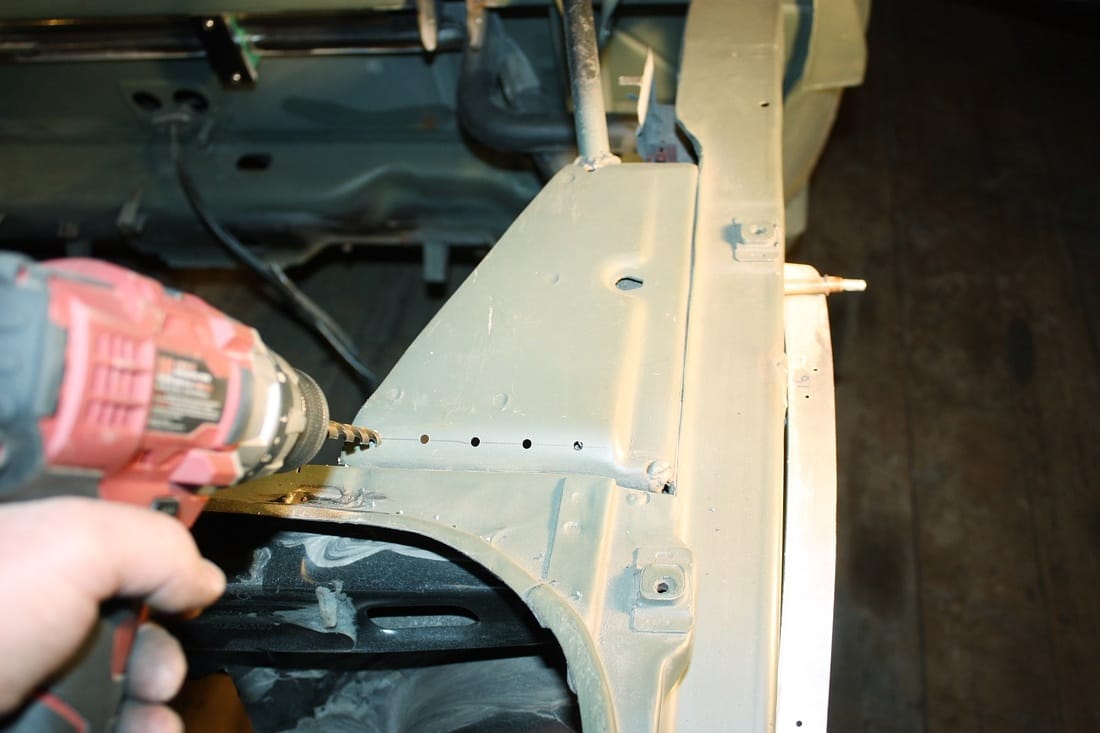
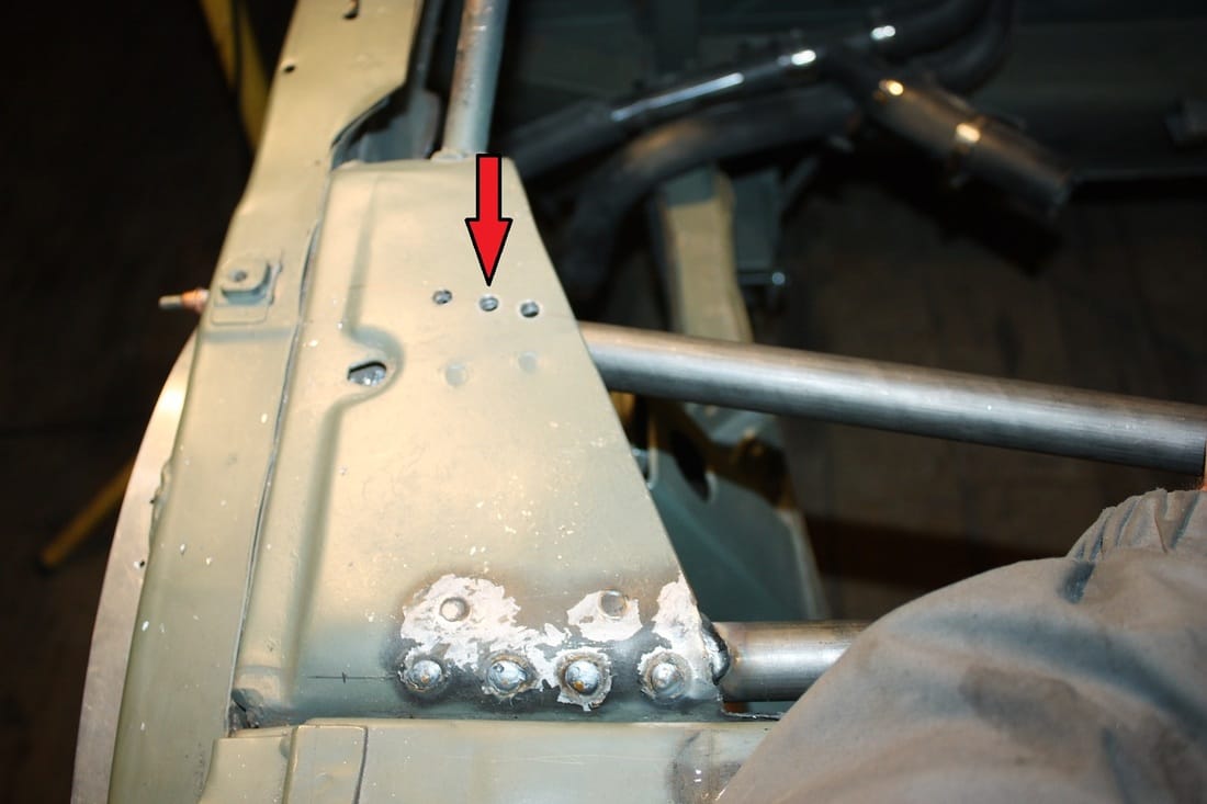
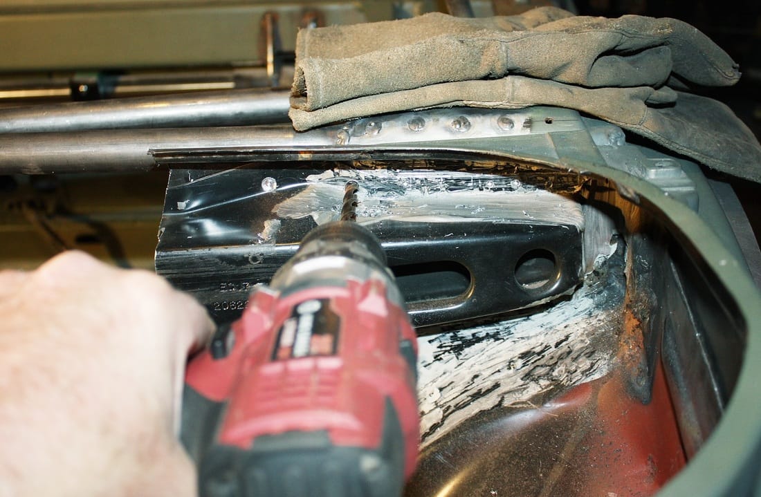
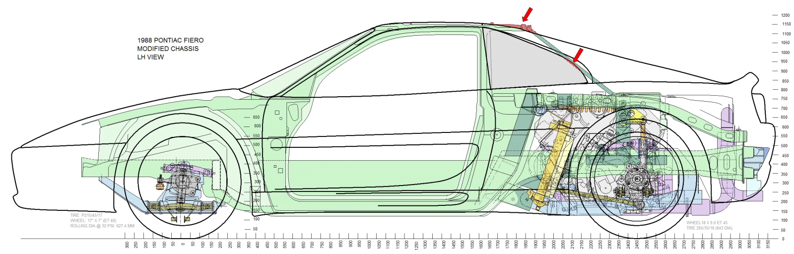
I chose to hold off welding the lower window frame in place until I was certain I could modify the roof line to meet up with the top of the glass. That meant turning my focus on the roof. First, I drilled out a few spot welds to get rid of the unnecessary drip flange:
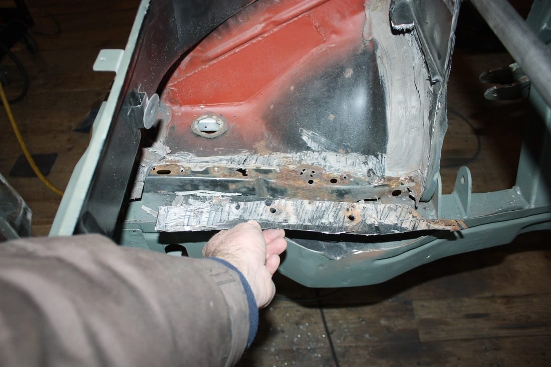
Like the B-pillar, the Fiero roof is a hollow structure formed of an inner and outer skin spot welded along flanges made for that purpose. When the original owner cut away the B-pillar, it opened up the aft portion of the roof chamber. This gave me access to the channel running fore and aft along the top of the door frame, and ultimately where I needed to anchor my new C-pillars. But first I had to gut the foam injected by the factory from the space inside the roof chamber:
That stuff was a real pain the you-know-what to get out. It was sticky and very tough, but I managed to clear enough of it out of the way for my purposes.
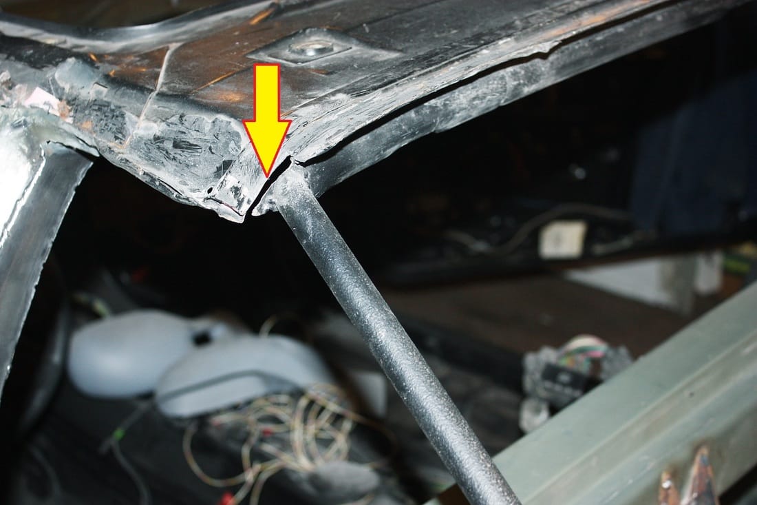
Next, I had to bend the factory down-turn in the roof out of the way to have a clear path into the channel above the door. It was easy since the outer skin of the roof was separated from the inner skin along that edge:
Argggh! More foam!
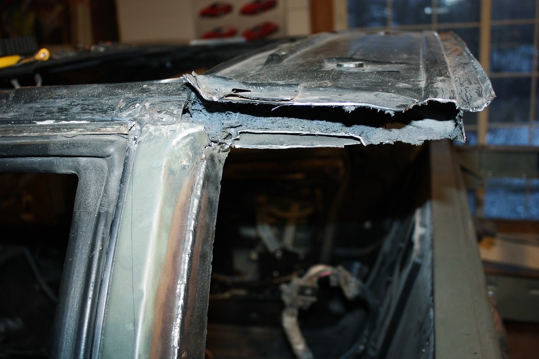
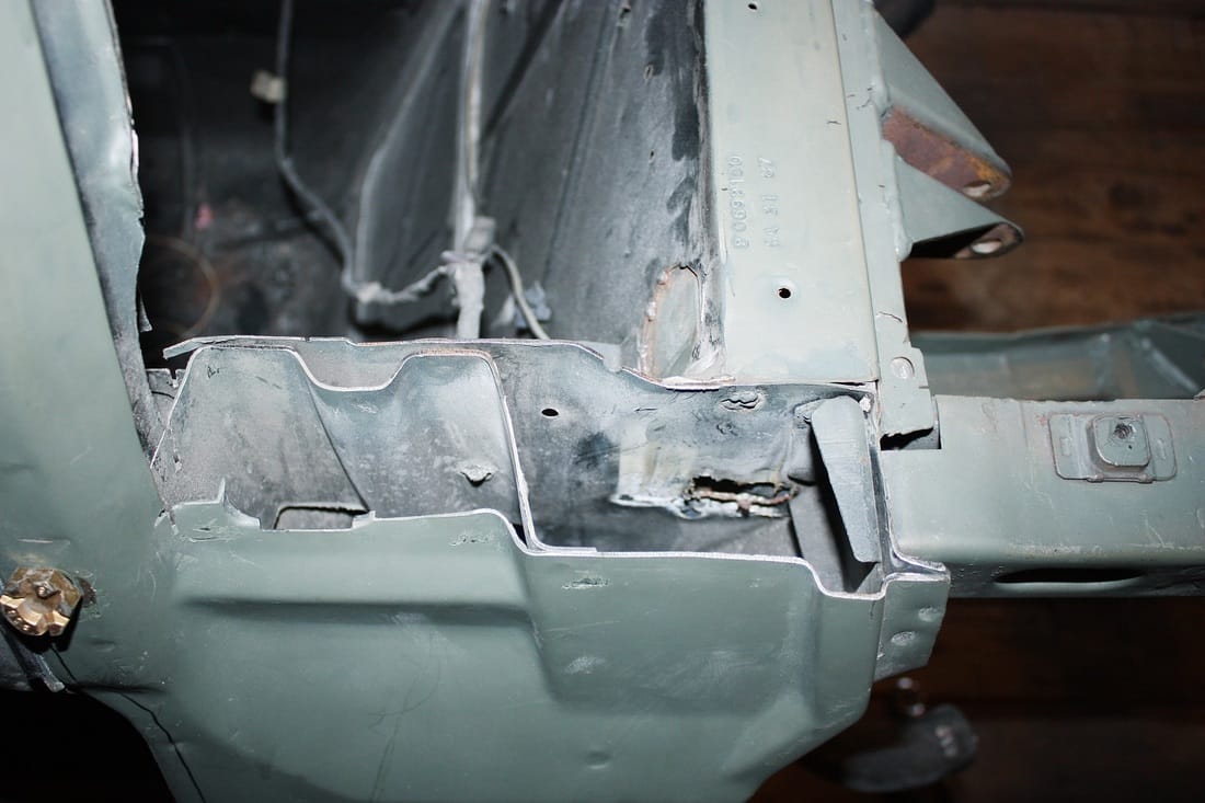
After some more digging, scraping, and minor flesh wounds, I finally cleared enough foam and metal out of the way for a clear shot into the upper door frame:
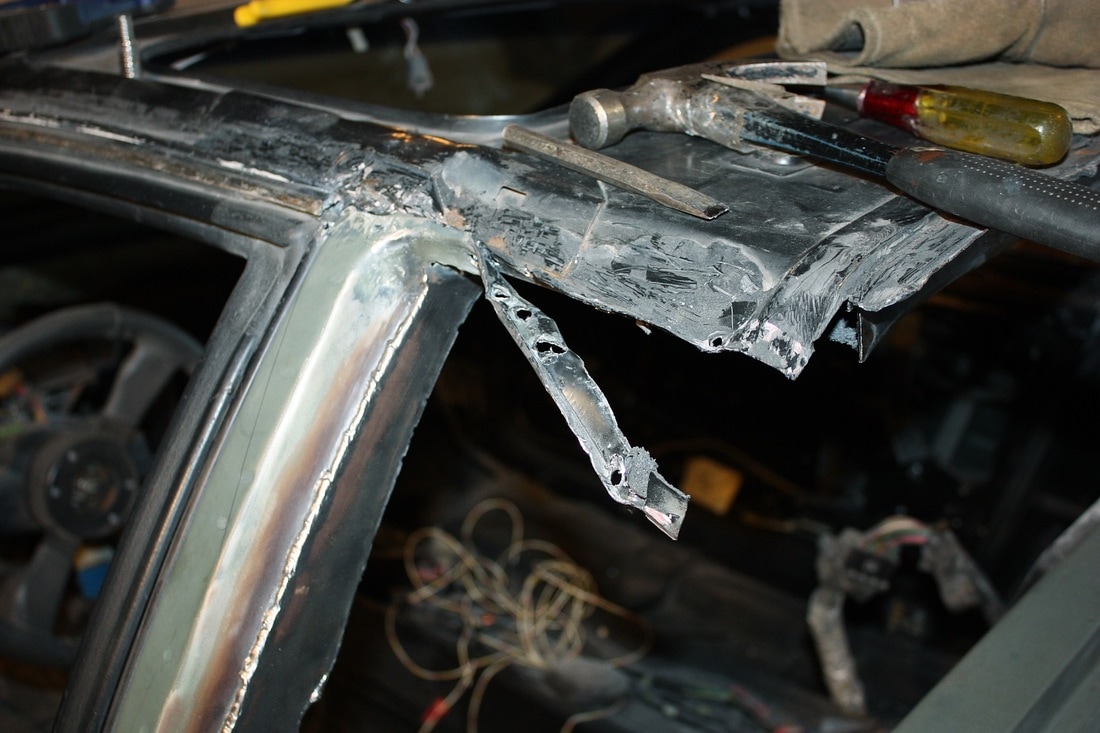
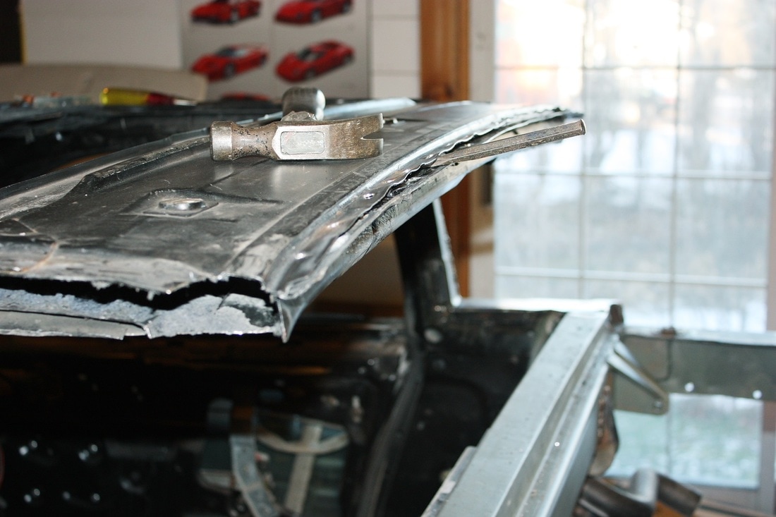
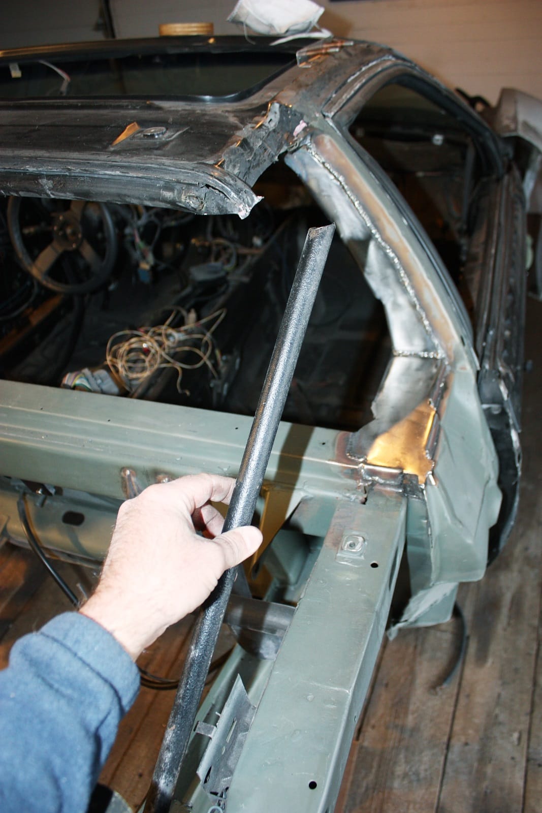
At this point I was ready to try bending the rear edge of the metal roof downwards to achieve a better profile. Having read how owners of the Air Dynamics F355 kit essentially jump up and down on it, I decided there had to be a better way. Besides, simply bending it down wasn't going to be enough... I also had to shorten it several inches for it to meet up with the top edge of the MR2 glass. While looking over the construction of the roof, an idea hit me:
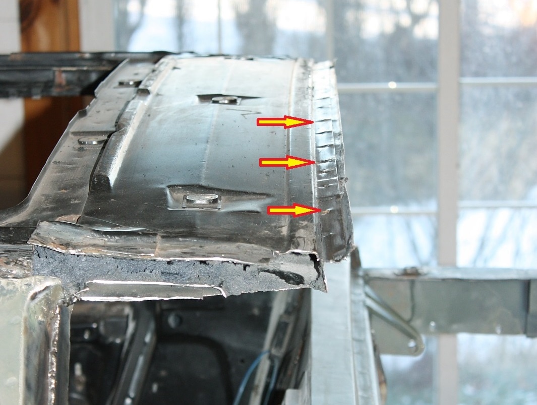
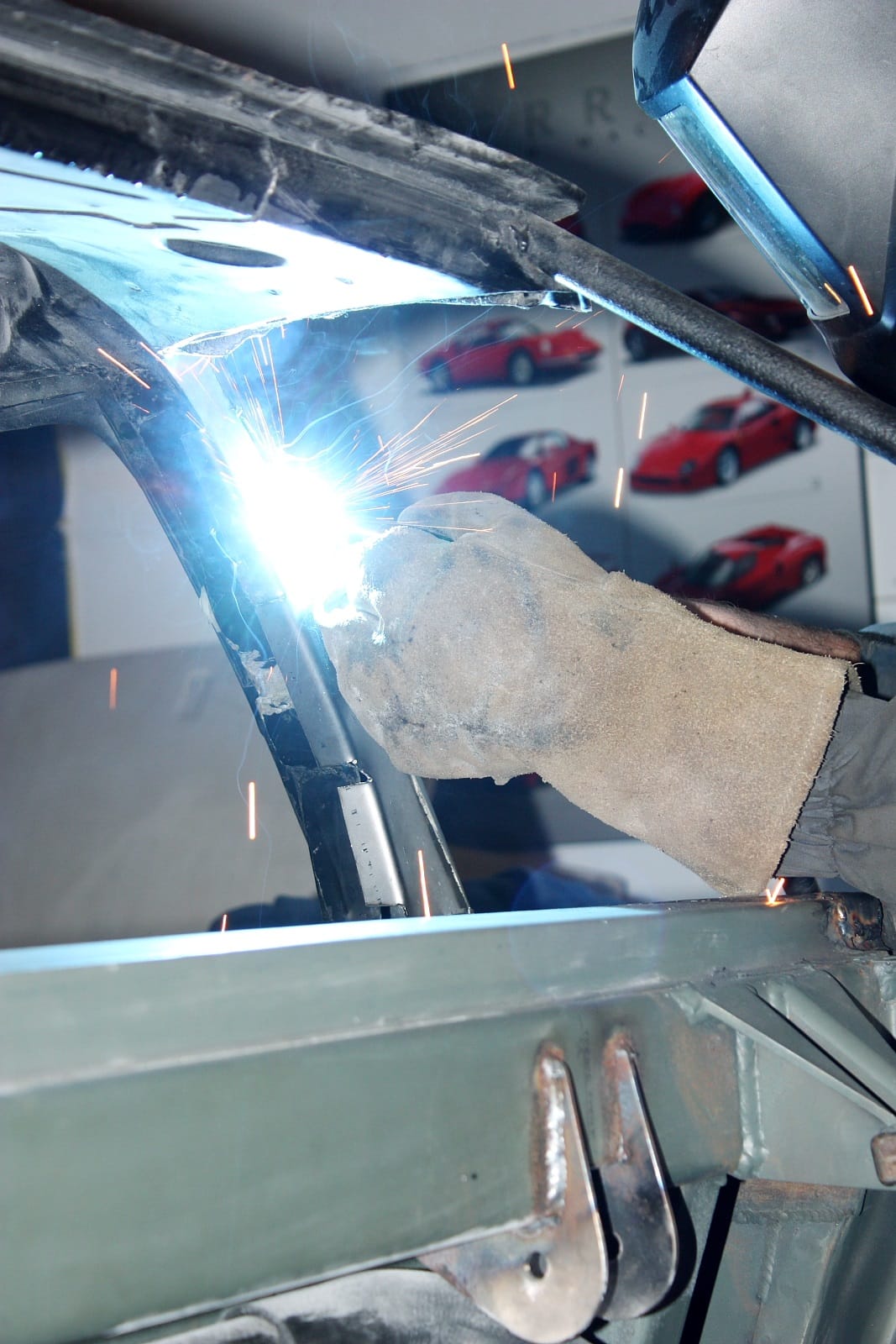
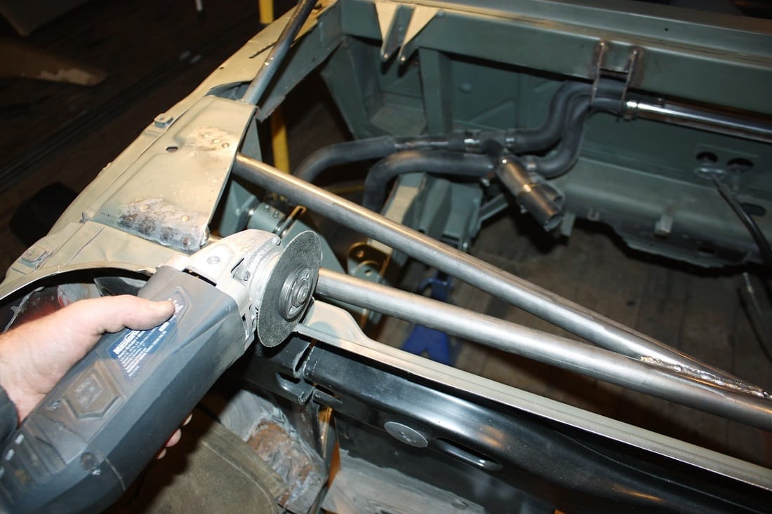
By drilling out the spot welds along the rear weld flange, I could separate the inner and outer roof skins and offset the inner skin toward the front of the car. That way I'd be able to reuse the integral upper window frame, and it would be a cinch to bend the separated roof skins down to where I needed them. So I started drilling spot welds and chiselling them apart:
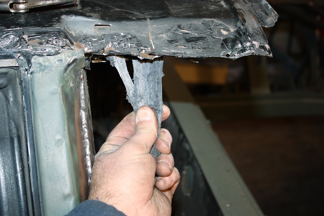
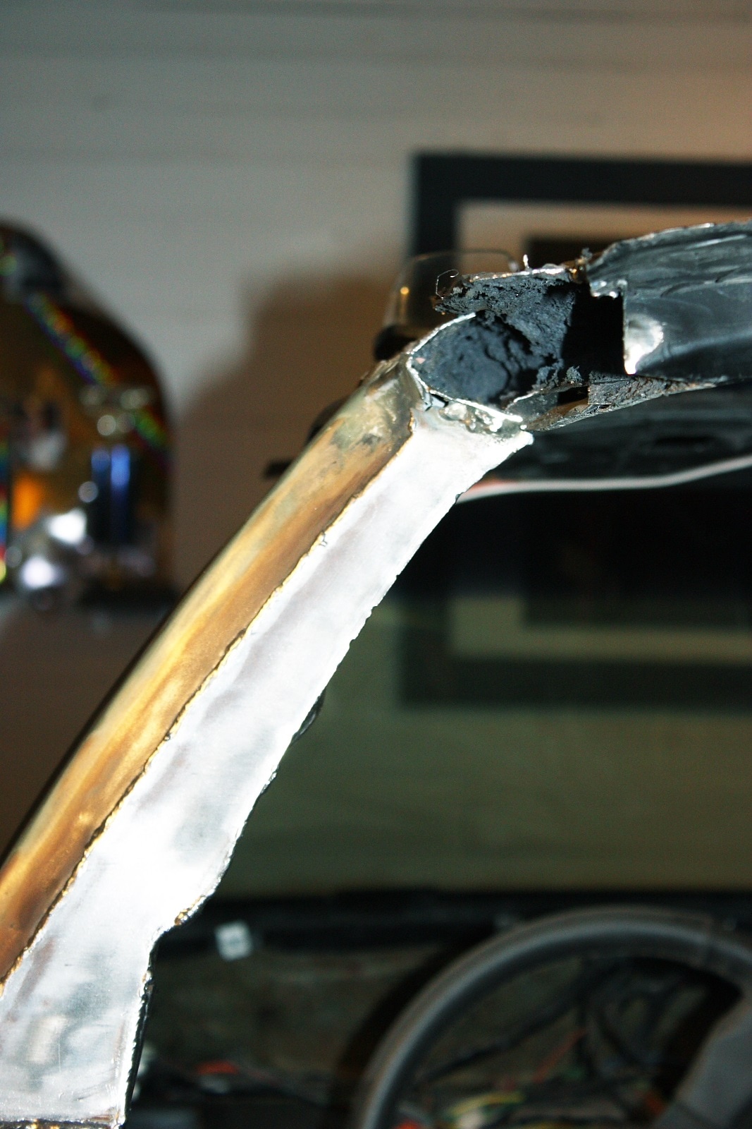
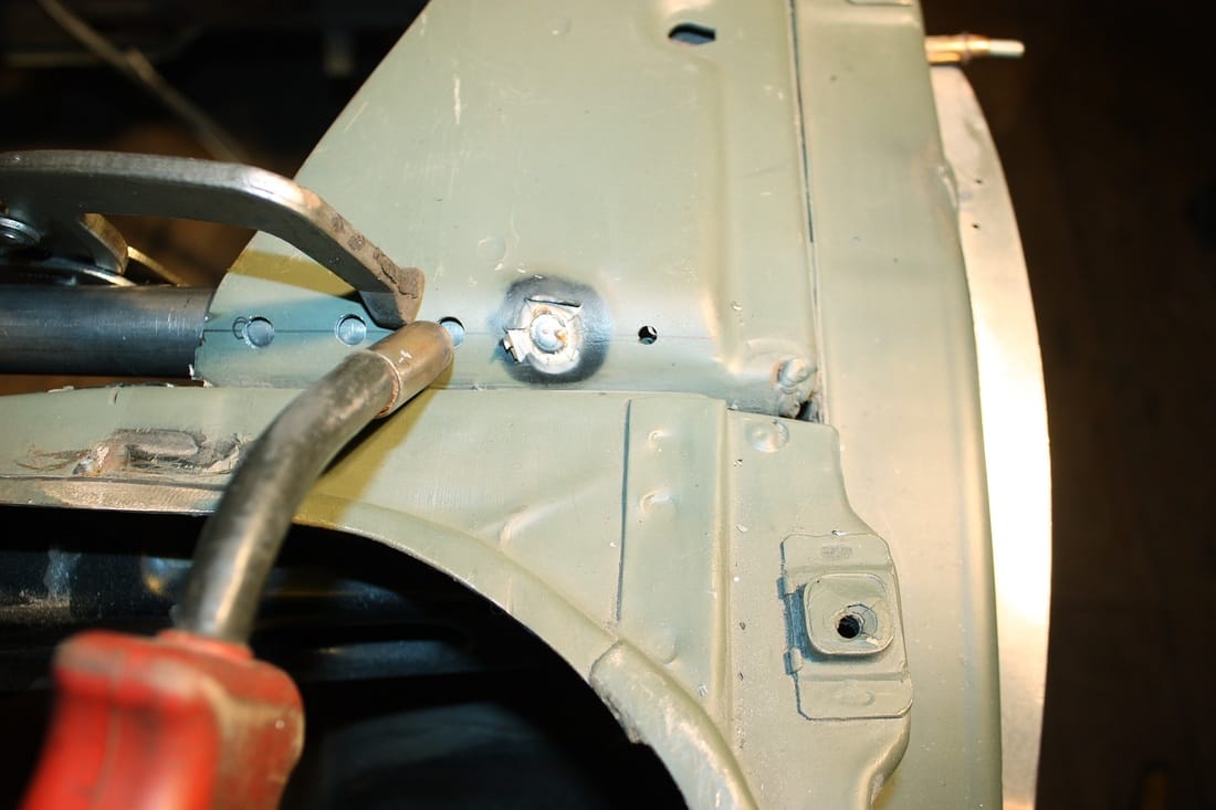
By keeping the lower half of the weld flange intact (rather than simply lopping it off with a cut-off wheel) I'll be able to reuse it to reattach the inner skin in its new offset location later on. Once the rear edge had been freed up, a carefully planned slice on the inside roof skin...
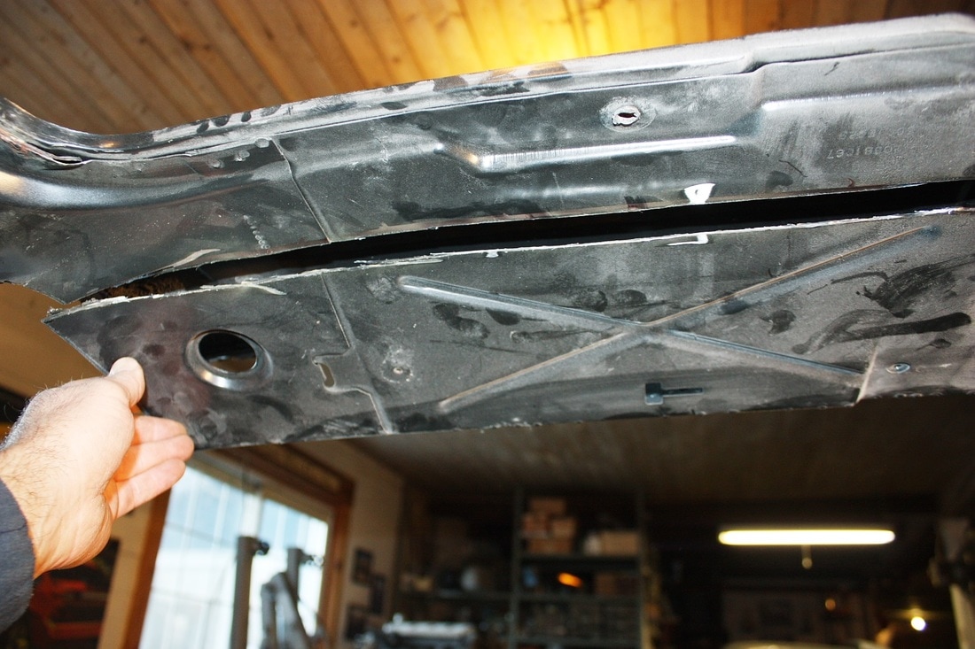
... was all that was needed to remove it.
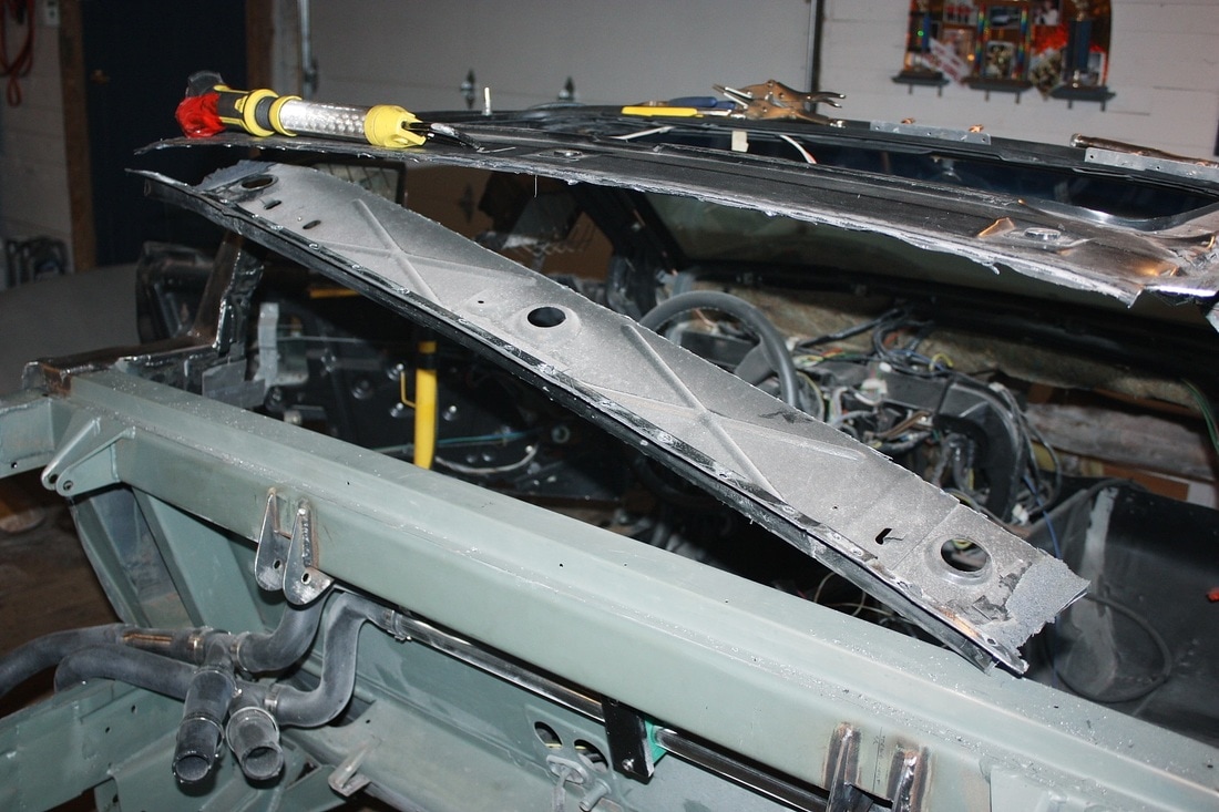
The rear edge of the roof skin was now as flexible as a rubber band. Before I could reweld the inner skin in its new offset and lowered position though, I would have needed to mock up the window again, but I wasn't quite ready for that. So I set the inner roof skin aside while I tackled the next challenge: the C-Pillars.


 RSS Feed
